6. SYSTEM I/O
6.1Serial Port Connectors
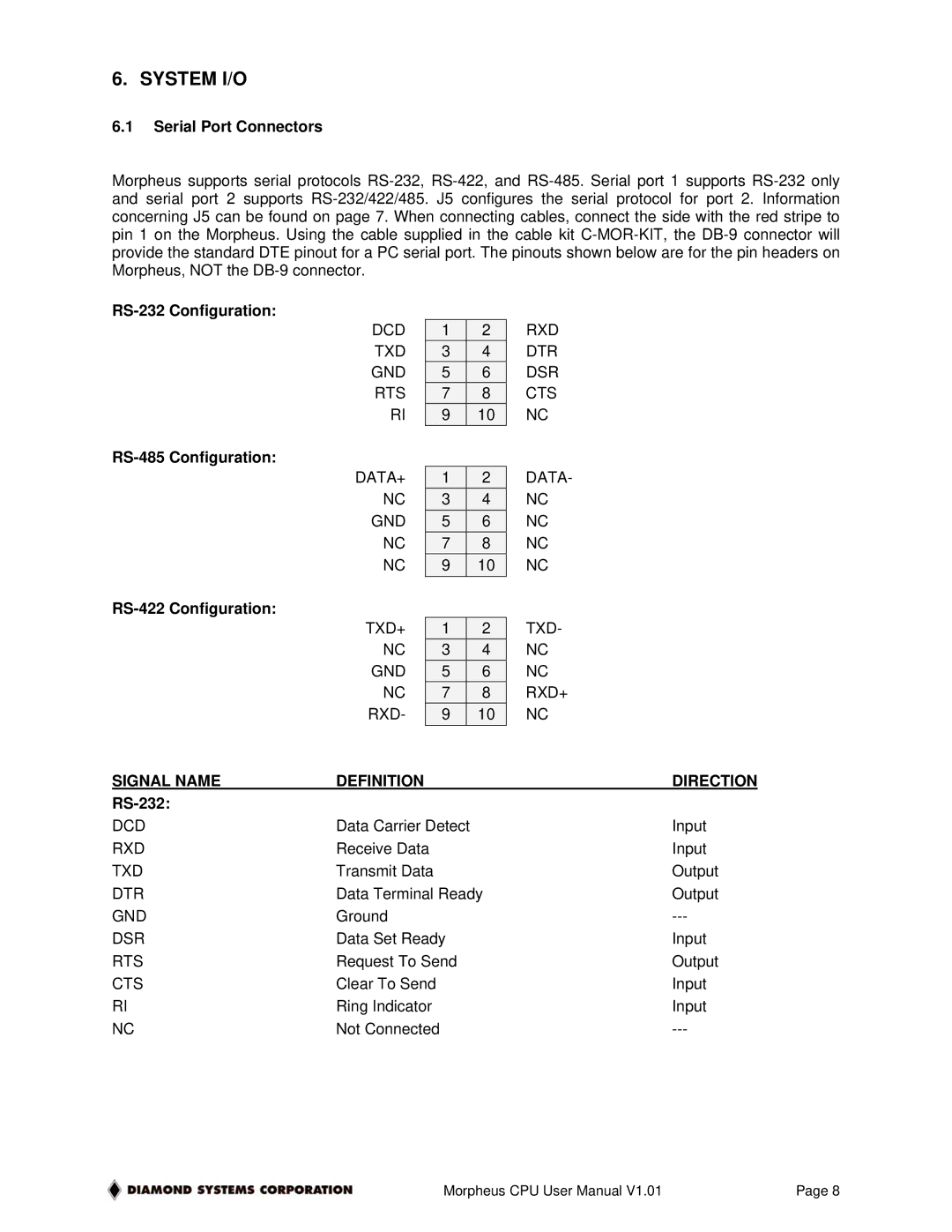
Morpheus supports serial protocols
|
|
|
|
| RXD | |
| DCD |
| 1 |
| 2 | |
| TXD |
| 3 |
| 4 | DTR |
| GND |
| 5 |
| 6 | DSR |
| RTS |
| 7 |
| 8 | CTS |
| RI |
| 9 |
| 10 | NC |
|
|
|
|
|
| |
| DATA+ |
| 1 |
| 2 | DATA- |
| NC |
| 3 |
| 4 | NC |
| GND |
| 5 |
| 6 | NC |
| NC |
| 7 |
| 8 | NC |
| NC |
| 9 |
| 10 | NC |
|
|
|
|
| TXD- | |
| TXD+ |
| 1 |
| 2 | |
| NC |
| 3 |
| 4 | NC |
| GND |
| 5 |
| 6 | NC |
| NC |
| 7 |
| 8 | RXD+ |
| RXD- |
| 9 |
| 10 | NC |
SIGNAL NAME | DEFINITION |
|
|
| DIRECTION | |
|
|
|
|
|
|
|
DCD | Data Carrier Detect |
| Input | |||
RXD | Receive Data |
|
|
| Input | |
TXD | Transmit Data |
|
|
| Output | |
DTR | Data Terminal Ready | Output | ||||
GND | Ground |
|
|
| ||
DSR | Data Set Ready |
| Input | |||
RTS | Request To Send |
| Output | |||
CTS | Clear To Send |
|
|
| Input | |
RI | Ring Indicator |
|
|
| Input | |
NC | Not Connected |
|
|
| ||
Morpheus CPU User Manual V1.01 | Page 8 |
