Response Er6c Assembly
A
![]()
![]()
B
N
| |
|
| |
C | |
|
Part |
| Description |
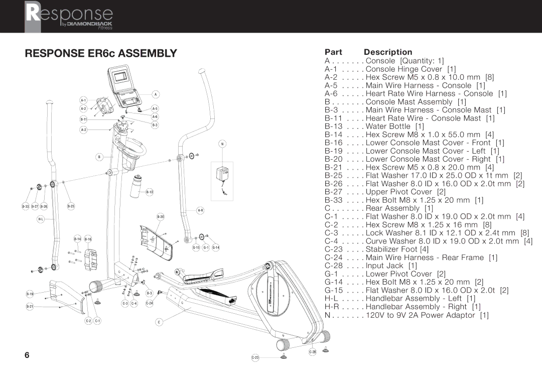
A . . | . | Console [Quantity: 1] |
. | . Console Hinge Cover [1] | |
. | . Hex Screw M5 x 0.8 x 10.0 mm [8] | |
. | . Main Wire Harness - Console [1] | |
. | . Heart Rate Wire Harness - Console [1] |
B. . . Console Mast Assembly [1]
. | . Main Wire Harness - Console Mast | [1] |
|
| |||
. | Heart Rate Wire - Console Mast | [1] |
|
|
| ||
. | Water Bottle [1] |
|
|
|
|
| |
. | Hex Screw M8 x 1.0 x 55.0 mm | [4] |
|
|
| ||
. | Lower Console Mast Cover - Front | [1] |
|
| |||
. | Lower Console Mast Cover - Left | [1] |
|
| |||
. | Lower Console Mast Cover - Right | [1] |
|
| |||
. | Hex Screw M5 x 0.8 x 20.0 mm | [4] |
|
|
| ||
. | Flat Washer 17.0 ID x 25.0 OD x 1t mm | [2] | |||||
. | Flat Washer 8.0 ID x 16.0 OD x 2.0t mm | [2] | |||||
. | Upper Pivot Cover [2] |
|
|
|
|
| |
. | Hex Bolt M8 x 1.25 x 20 mm [1] |
|
|
|
| ||
C . . | . | Rear Assembly [1] |
|
|
|
|
|
. | . Flat Washer 8.0 ID x 19.0 OD x 2.0t mm | [4] | |||||
. | . Hex Screw M8 x 1.25 x 16 mm [8] |
|
|
| |||
. | . Lock Washer 8.1 ID x 12.1 OD x 2.4t mm | [8] | |||||
. | . Curve Washer 8.0 ID x 19.0 OD x 2.0t mm | [4] | |||||
. | Stabilizer Foot [4] |
|
|
|
|
| |
. | Main Wire Harness - Rear Frame | [1] |
|
| |||
. | Input Jack [1] |
|
|
|
|
| |
. | . Lower Pivot Cover [2] |
|
|
|
|
| |
. | Hex Bolt M8 x 1.25 x 20 mm [2] |
|
|
|
| ||
. | Flat Washer 8.0 ID x 16.0 OD x 2.0t | [2] |
|
| |||
. | . Handlebar Assembly - Left | [1] |
|
|
|
| |
. | . Handlebar Assembly - Right | [1] |
|
|
|
| |
N . . | . | 120V to 9V 2A Power Adaptor [1] |
|
|
| ||
6 | |