STEP 8: DVR REMOTE SETTING
1.Connect the DVR and monitor.
2.In the “Remote” setting, set the baud rate and ID the same as the “Peripheral” setting on the video web server. Set the remote mode to
A. 1 / 4 CH DVR
B. 4 / 9 / 16 CH DMR
(MENU)
TIMER
CAMERA RECORD ALARM DWELL REMOTE SYSTEM EVENT
(MENU)
SEARCH
TIMER
RECORD CAMERA SYSTEM EVENT
(REMOTE)
REMOTE MODE :
BAUD RATE : 2400
ID : 001
(SYSTEM)
:
:
REMOTE MODE :
BAUD RATE : 2400
REMOTE ID : 001
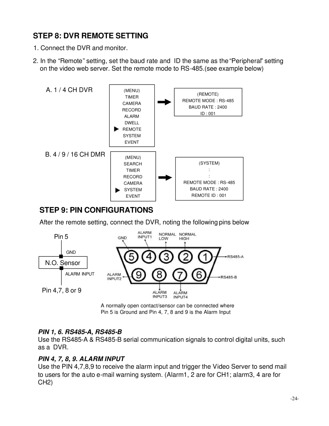
STEP 9: PIN CONFIGURATIONS
After the remote setting, connect the DVR, noting the following pins below
Pin 5
GND
N.O. Sensor
ALARM INPUT
Pin 4,7, 8 or 9
A normally open contact/sensor can be connected where
Pin 5 is Ground and Pin 4, 7, 8 and 9 is the Alarm Input
PIN 1, 6.
Use the
PIN 4, 7, 8, 9. ALARM INPUT
Use the PIN 4,7,8,9 to receive the alarm input and trigger the Video Server to send mail to users for the a uto