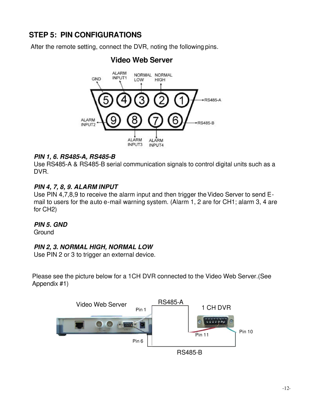
STEP 5: PIN CONFIGURATIONS
After the remote setting, connect the DVR, noting the following pins.
Video Web Server
PIN 1, 6.
Use
PIN 4, 7, 8, 9. ALARM INPUT
Use PIN 4,7,8,9 to receive the alarm input and then trigger the Video Server to send E- mail to users for the auto
PIN 5. GND
Ground
PIN 2, 3. NORMAL HIGH, NORMAL LOW
Use PIN 2 or 3 to trigger an external device.
Please see the picture below for a 1CH DVR connected to the Video Web Server.(See Appendix #1)
Video Web Server
Pin 1
1 CH DVR
Pin 6
Pin 11
Pin 10