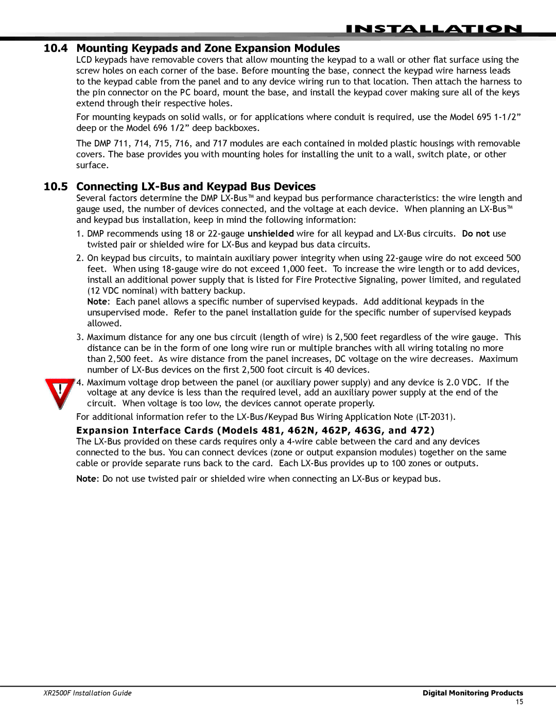
XR2500F specifications
The DMP Electronics XR2500F is an advanced and versatile electronic device designed to cater to a wide range of applications including industrial automation, robotics, and smart home technologies. Known for its robust performance and reliable functionalities, the XR2500F stands out as a leading option in the market.One of the main features of the XR2500F is its powerful processing unit, which ensures efficient handling of complex tasks and data processing. With a clock speed of up to 2.5 GHz, the device is capable of multitasking, enabling users to run multiple applications simultaneously without compromising performance. This makes the XR2500F an ideal choice for applications that require real-time data processing and analysis.
The XR2500F is equipped with an extensive array of connectivity options, including Wi-Fi, Bluetooth, and Ethernet capabilities. This allows for seamless integration with various devices and networks. The wireless options facilitate easy communication with cloud services and other IoT devices, making it suitable for smart home automation systems, where synchronization and control are critical.
In terms of memory, the XR2500F offers significant storage capacity, with options that can accommodate up to 64GB of RAM and 512GB of flash storage. This ample memory ensures that users can store large amounts of data and run memory-intensive applications without experiencing slowdowns. Additionally, the device supports expandable memory options, allowing for future upgrades to meet growing demands.
The XR2500F also incorporates advanced security technologies to protect sensitive data. Features like end-to-end encryption and secure boot processes safeguard against unauthorized access and data breaches. This is particularly important in industrial settings where data integrity is critical for operational safety.
Another remarkable characteristic of the XR2500F is its energy efficiency. Designed with the latest power management technologies, the device minimizes energy consumption while maximizing performance. This not only reduces operational costs but also aligns with green technology initiatives.
Overall, the DMP Electronics XR2500F is a high-performance electronic device that combines powerful processing, extensive connectivity, robust memory, enhanced security, and energy efficiency. Its versatility and reliability make it a preferred choice for professionals seeking innovative solutions in automation and control systems.

