of 200W (connection impedance 50 ohms) with the DPA 4120, respectively 400W (connection impedance 25 ohms) with the DPA 4140. Connection is performed using the 100V output (17) (see also figure 3). In a few special cases it is also possible to operate the loudspeaker systems with 70V or 50V output voltage (see also paragraph 7).
Caution It is possible that during operation
5.3SINGLE CALL and obligatory reception relays OVERRIDE BYPASS
Combined with the PROMATRIX manager DPM 4000 or other external controls it is also possible to transmit single or collective calls with obligatory reception; i. e. bridging of possibly existing volume controls of the loudspeaker systems. For details on how to connect the outputs, please refer to figure 3; for the connection of relays, please refer to paragraph 5.6 respectively the PROMATRIX handbook.
5.4POWER OUTPUT for low impedance loudspeaker systems
Switching the output to 4 ohms allows the connection of low impedance loudspeaker systems
5.5MONITOR output
The MONITOR output (16) on the NRS 90225 allows the connection of an additional power amplifier for monitoring purposes. The low impedance output is electronically balanced, which offers the possibility to achieve cable lengths of up to 200 m. Connection is performed via the REMOTE CONTROL
Note: Functioning changes in the models DPA 4120 (starting with serial numbers: 100 11) and DPA 4140 (starting with serial numbers: 100 11) in association with the input module NRS 90225: To achieve reliable attenuation of switching noise (knacks), the monitor output stays muted as long as the
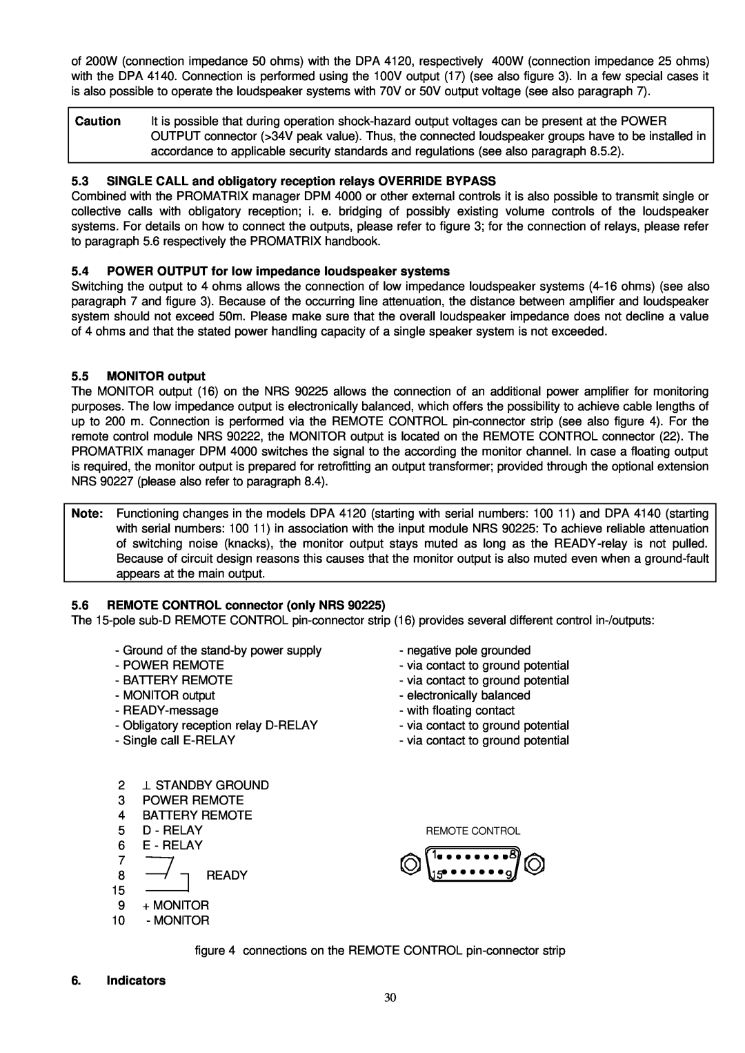
5.6REMOTE CONTROL connector (only NRS 90225)
The
- Ground of the | - negative pole grounded |
- POWER REMOTE | - via contact to ground potential |
- BATTERY REMOTE | - via contact to ground potential |
- MONITOR output | - electronically balanced |
- | - with floating contact |
- Obligatory reception relay | - via contact to ground potential |
- Single call | - via contact to ground potential |
2⊥ STANDBY GROUND
3POWER REMOTE
4BATTERY REMOTE
5 | D - RELAY | REMOTE CONTROL |
6 | E - RELAY |
|
7 |
|
|
8 |
| READY |
15
9+ MONITOR
10- MONITOR
figure 4 connections on the REMOTE CONTROL
6.Indicators
30