DX Switchbox (DX-ARC-SWB) – Installation Manual

4.2Seat Switches

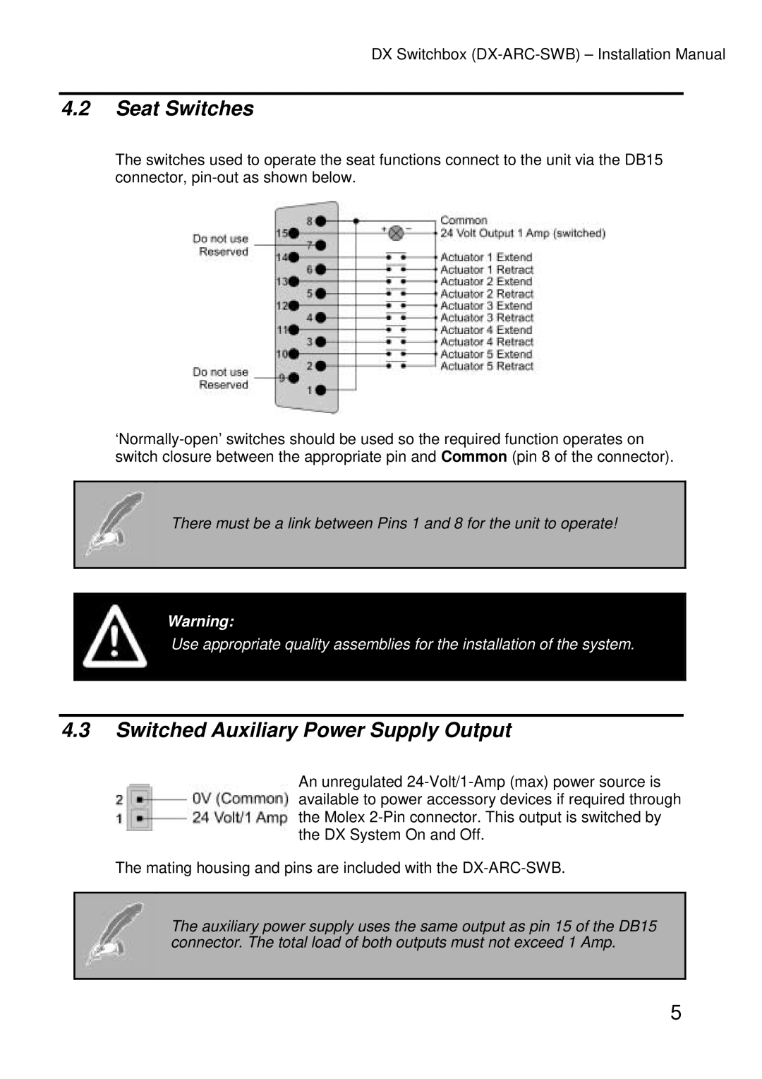
The switches used to operate the seat functions connect to the unit via the DB15 connector, pin-out as shown below.

‘Normally-open’ switches should be used so the required function operates on switch closure between the appropriate pin and Common (pin 8 of the connector).

There must be a link between Pins 1 and 8 for the unit to operate!

Warning:

Use appropriate quality assemblies for the installation of the system.

4.3Switched Auxiliary Power Supply Output

An unregulated 24-Volt/1-Amp (max) power source is available to power accessory devices if required through the Molex 2-Pin connector. This output is switched by the DX System On and Off.

The mating housing and pins are included with the DX-ARC-SWB.

The auxiliary power supply uses the same output as pin 15 of the DB15 connector. The total load of both outputs must not exceed 1 Amp.

5
Page 9
Image 9
Dynamic Distributors DX-ARC-SWB installation manual Seat Switches, Switched Auxiliary Power Supply Output