CONNECTING POWER TO THE CM9760-MXB

NOTE: A CM9760-MXB operates on 120 VAC, 60 Hz. A CM9760-MXB-X operates on 230 VAC, 50 Hz.

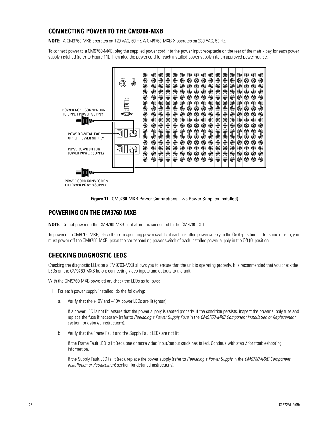
To connect power to a CM9760-MXB, plug the supplied power cord into the power input receptacle on the rear of the matrix bay for each power supply installed (refer to Figure 11). Then plug the power cord for each installed power supply into an approved power source.

POWER CORD CONNECTION TO UPPER POWER SUPPLY

POWER SWITCH FOR UPPER POWER SUPPLY

POWER SWITCH FOR LOWER POWER SUPPLY

Alarm

Black


Out

RS-422

RS-422

POWER CORD CONNECTION

TO LOWER POWER SUPPLY

Figure 11. CM9760-MXB Power Connections (Two Power Supplies Installed)

POWERING ON THE CM9760-MXB

NOTE: Do not power on the CM9760-MXB until after it is connected to the CM9700-CC1.

To power on a CM9760-MXB, place the corresponding power switch of each installed power supply in the On (I) position. If, for some reason, you must power off the CM9760-MXB, place the corresponding power switch of each installed power supply in the Off (0) position.

CHECKING DIAGNOSTIC LEDS

Checking the diagnostic LEDs on a CM9760-MXB allows you to ensure that the unit is operating properly. It is recommended that you check the LEDs on the CM9760-MXB before connecting video inputs and outputs to the unit.

With the CM9760-MXB powered on, check the LEDs as follows:

1.For each power supply installed, do the following:

a.Verify that the +10V and –10V power LEDs are lit (green).

If a power LED is not lit, ensure that the power supply is seated properly. If the condition persists, inspect the power supply fuse and replace the fuse if necessary (refer to Replacing a Power Supply Fuse in the CM9760-MXB Component Installation or Replacement section for detailed instructions).

b.Verify that the Frame Fault and the Supply Fault LEDs are not lit.

If the Frame Fault LED is lit (red), one or more video input/output cards has failed. Continue with step 2 for troubleshooting information.

If the Supply Fault LED is lit (red), replace the power supply (refer to Replacing a Power Supply in the CM9760-MXB Component Installation or Replacement section for detailed instructions).

26

C1572M (9/05)

Page 26
Image 26
Pelco System 9760 manual Connecting Power to the CM9760-MXB, Powering on the CM9760-MXB, Checking Diagnostic Leds