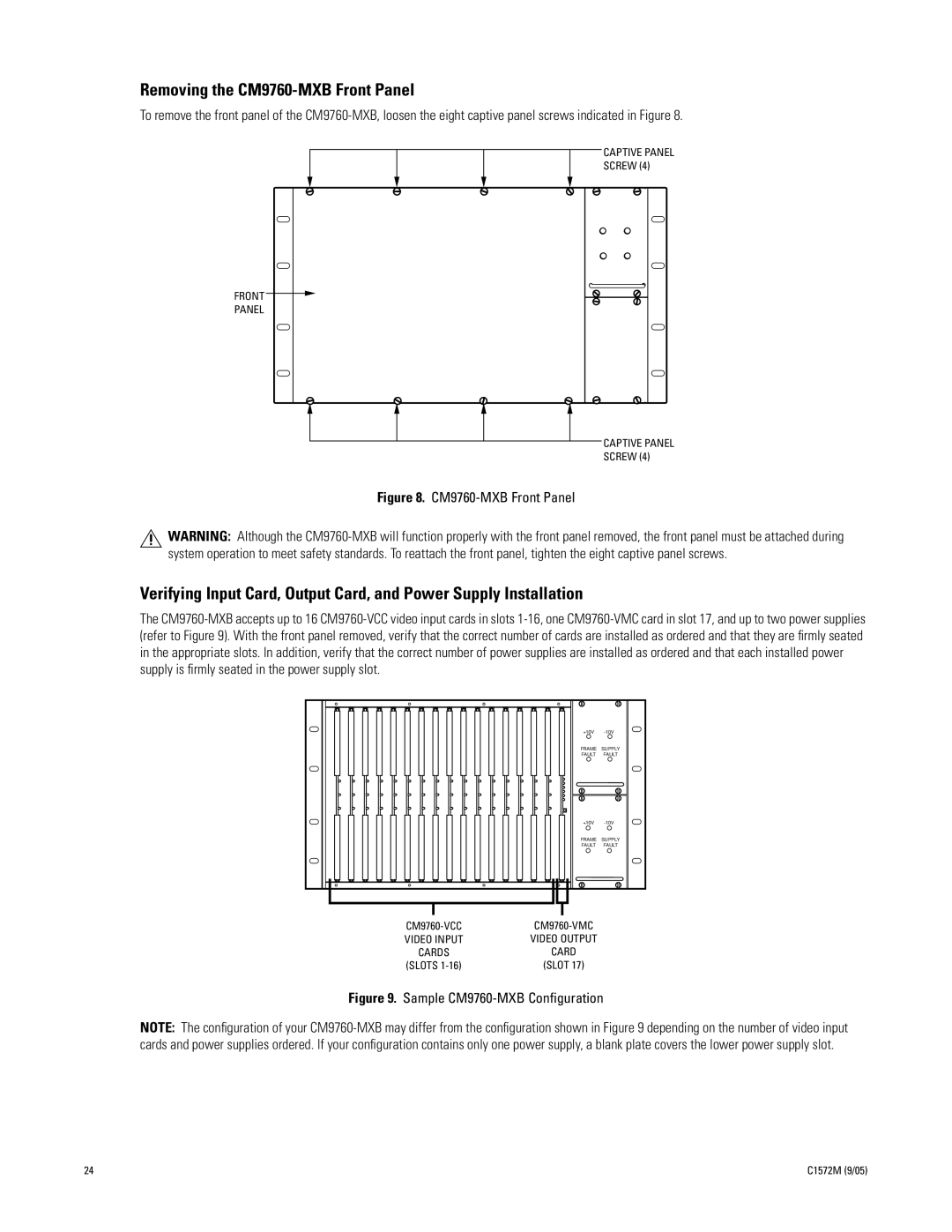
Removing the CM9760-MXB Front Panel
To remove the front panel of the
CAPTIVE PANEL
SCREW (4)
FRONT
PANEL
CAPTIVE PANEL
SCREW (4)
Figure 8. CM9760-MXB Front Panel
WARNING: Although the
Verifying Input Card, Output Card, and Power Supply Installation
The
+10V
FRAME SUPPLY
FAULT FAULT
+10V
FRAME SUPPLY
FAULT FAULT
VIDEO INPUT | VIDEO OUTPUT |
CARDS | CARD |
(SLOTS | (SLOT 17) |
Figure 9. Sample CM9760-MXB Configuration
NOTE: The configuration of your
24 | C1572M (9/05) |