PIN 2
PIN 1
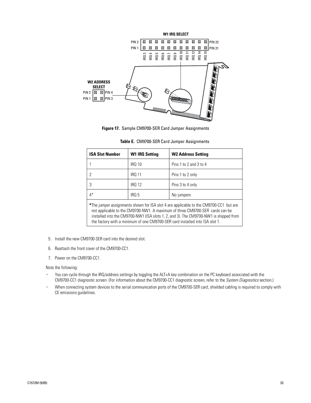
W1 IRQ SELECT
PIN 22
PIN 21
IRQ 3 | IRQ 4 | IRQ 5 | IRQ 6 | IRQ 7 | IRQ 9 | IRQ 10 | IRQ 11 | IRQ 12 | IRQ 14 | IRQ 15 |
W2 ADDRESS
SELECT
PIN 2
PIN 1
PIN 4
PIN 3
Figure 17. Sample CM9700-SER Card Jumper Assignments
Table E. CM9700-SER Card Jumper Assignments
ISA Slot Number | W1 IRQ Setting | W2 Address Setting | |
|
|
| |
1 | IRQ 10 | Pins 1 to 2 and 3 to 4 | |
|
|
| |
2 | IRQ 11 | Pins 1 to 2 only | |
|
|
|
|
3 | IRQ | 12 | Pins 3 to 4 only |
|
|
|
|
4* | IRQ | 5 | No jumpers |
|
|
|
|
*The jumper assignments shown for ISA slot 4 are applicable to the
5.Install the new
6.Reattach the front cover of the
7.Power on the
Note the following:
•You can cycle through the IRQ/address settings by toggling the ALT+A key combination on the PC keyboard associated with the
•When connecting system devices to the serial communication ports of the
C1572M (9/05) | 33 |