Pelco System 9760 manual Rear View, Illustrates the rear of the CM9700-CC1

Models: System 9760

1 148
Download 148 pages 41.95 Kb
Page 84
Image 84

REAR VIEW

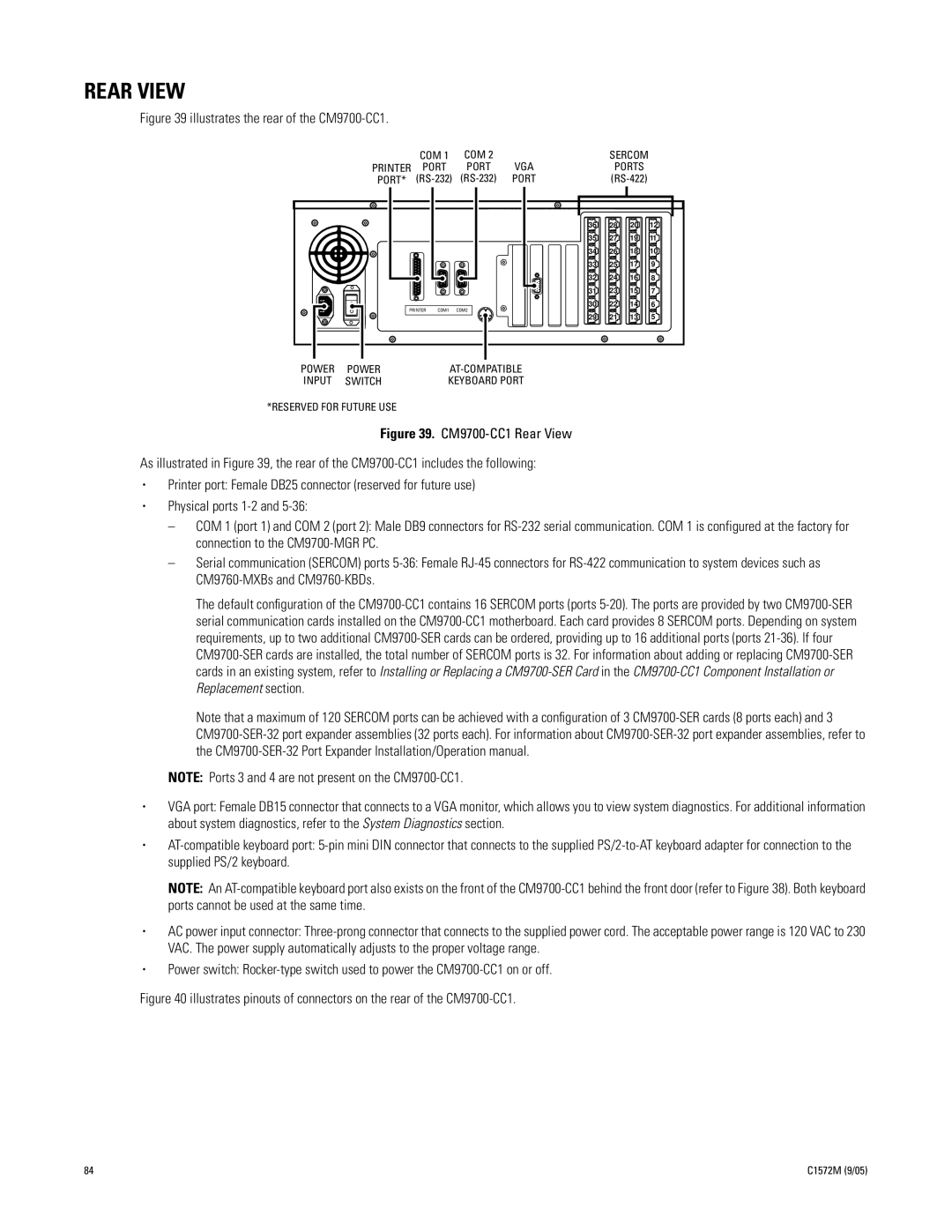
Figure 39 illustrates the rear of the CM9700-CC1.


COM 1

COM 2


SERCOM

PRINTER

PORT

PORT

VGA

PORTS

PORT*

(RS-232)

(RS-232)

PORT

(RS-422)


36

28

20

12


35

27

19

11


34

26

18

10


33

25

17

9


32

24

16

8


31

23

15

7


30

22

14

6

PRINTER

COM1

COM2


29

21

13

5

POWER

POWER

AT-COMPATIBLE

INPUT

SWITCH

KEYBOARD PORT

*RESERVED FOR FUTURE USE

Figure 39. CM9700-CC1 Rear View

As illustrated in Figure 39, the rear of the CM9700-CC1 includes the following:

Printer port: Female DB25 connector (reserved for future use)

Physical ports 1-2 and 5-36:

COM 1 (port 1) and COM 2 (port 2): Male DB9 connectors for RS-232 serial communication. COM 1 is configured at the factory for connection to the CM9700-MGR PC.

Serial communication (SERCOM) ports 5-36: Female RJ-45 connectors for RS-422 communication to system devices such as CM9760-MXBs and CM9760-KBDs.

The default configuration of the CM9700-CC1 contains 16 SERCOM ports (ports 5-20). The ports are provided by two CM9700-SER serial communication cards installed on the CM9700-CC1 motherboard. Each card provides 8 SERCOM ports. Depending on system requirements, up to two additional CM9700-SER cards can be ordered, providing up to 16 additional ports (ports 21-36). If four CM9700-SER cards are installed, the total number of SERCOM ports is 32. For information about adding or replacing CM9700-SER cards in an existing system, refer to Installing or Replacing a CM9700-SER Card in the CM9700-CC1 Component Installation or Replacement section.

Note that a maximum of 120 SERCOM ports can be achieved with a configuration of 3 CM9700-SER cards (8 ports each) and 3 CM9700-SER-32 port expander assemblies (32 ports each). For information about CM9700-SER-32 port expander assemblies, refer to the CM9700-SER-32 Port Expander Installation/Operation manual.

NOTE: Ports 3 and 4 are not present on the CM9700-CC1.

VGA port: Female DB15 connector that connects to a VGA monitor, which allows you to view system diagnostics. For additional information about system diagnostics, refer to the System Diagnostics section.

AT-compatible keyboard port: 5-pin mini DIN connector that connects to the supplied PS/2-to-AT keyboard adapter for connection to the supplied PS/2 keyboard.

NOTE: An AT-compatible keyboard port also exists on the front of the CM9700-CC1 behind the front door (refer to Figure 38). Both keyboard ports cannot be used at the same time.

AC power input connector: Three-prong connector that connects to the supplied power cord. The acceptable power range is 120 VAC to 230 VAC. The power supply automatically adjusts to the proper voltage range.

Power switch: Rocker-type switch used to power the CM9700-CC1 on or off.

Figure 40 illustrates pinouts of connectors on the rear of the CM9700-CC1.

84

C1572M (9/05)

Page 84
Image 84
Pelco System 9760 manual Rear View, Illustrates the rear of the CM9700-CC1