REPLACING A CM9760-VMC CARD
![]() WARNINGS:
WARNINGS:
•
•Electrostatic discharge (ESD) precautions must be observed when replacing a
Before replacing a
•The
•When installed in the matrix bay at the factory according to your system order, the S2 DIP switch and X55 and JP2 jumper settings on the
To replace the
1.Remove the front panel of the matrix bay.
2.Remove the
NOTE: Unless the audible alarm on the power supply has been disabled, the alarm beeps and the Frame Fault LED flashes red when the
3.Install the new
INSTALLING A CM9760-VMM VIDEO OUTPUT MODULE
![]() WARNINGS:
WARNINGS:
•
•Electrostatic discharge (ESD) precautions must be observed. Always wear a grounding strap connected to an approved grounding source when working on or near exposed electronic equipment.
•When installing a
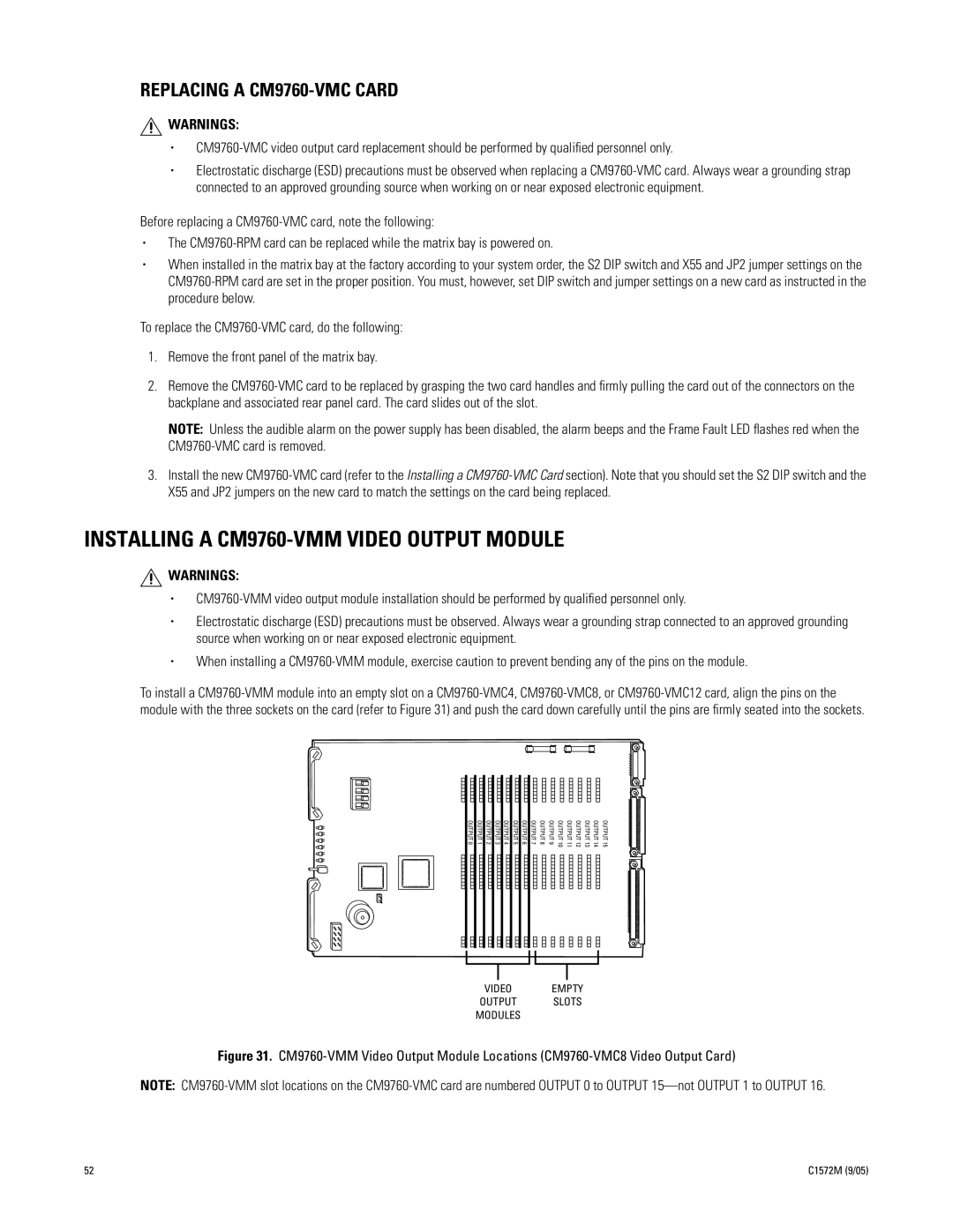
To install a
OUTPUT 0
OUTPUT 1
OUTPUT 2
OUTPUT 3
OUTPUT 4
OUTPUT 5
OUTPUT 6
OUTPUT7 | OUTPUT8 | OUTPUT9 | OUTPUT10 | OUTPUT11 | OUTPUT12 | OUTPUT13 | OUTPUT14 | OUTPUT15 |
VIDEO EMPTY
OUTPUT SLOTS
MODULES
Figure 31. CM9760-VMM Video Output Module Locations (CM9760-VMC8 Video Output Card)
NOTE:
52 | C1572M (9/05) |