Pelco System 9760 manual Front View, Illustrates the front of the CM9700-CC1

Models: System 9760

1 148
Download 148 pages 41.95 Kb
Page 83
Image 83

FRONT VIEW

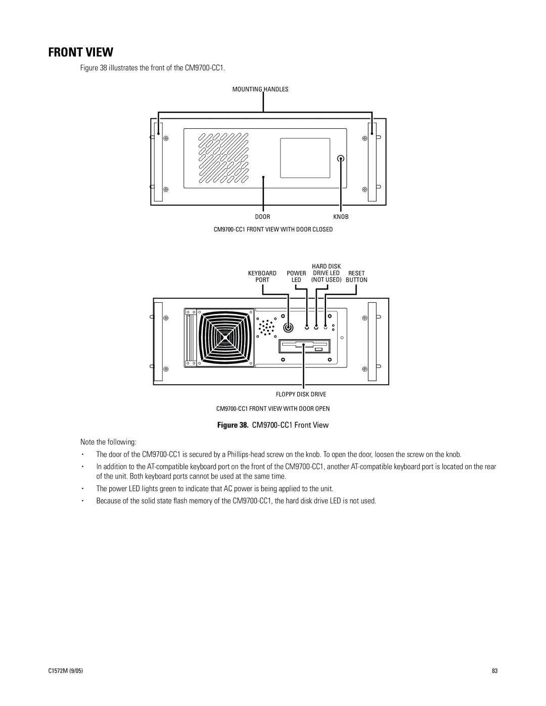
Figure 38 illustrates the front of the CM9700-CC1.

MOUNTING HANDLES

DOOR

KNOB

CM9700-CC1 FRONT VIEW WITH DOOR CLOSED


HARD DISK


KEYBOARD

POWER

DRIVE LED

RESET

PORT

LED

(NOT USED)

BUTTON

FLOPPY DISK DRIVE

CM9700-CC1 FRONT VIEW WITH DOOR OPEN

Figure 38. CM9700-CC1 Front View

Note the following:

The door of the CM9700-CC1 is secured by a Phillips-head screw on the knob. To open the door, loosen the screw on the knob.

In addition to the AT-compatible keyboard port on the front of the CM9700-CC1, another AT-compatible keyboard port is located on the rear of the unit. Both keyboard ports cannot be used at the same time.

The power LED lights green to indicate that AC power is being applied to the unit.

Because of the solid state flash memory of the CM9700-CC1, the hard disk drive LED is not used.

C1572M (9/05)

83

Page 83
Image 83
Pelco System 9760 manual Front View, Illustrates the front of the CM9700-CC1