INSTALLING OR REPLACING A CM9700-SER CARD
![]() WARNINGS:
WARNINGS:
•
•Electrostatic discharge (ESD) precautions must be observed when installing or replacing a
The
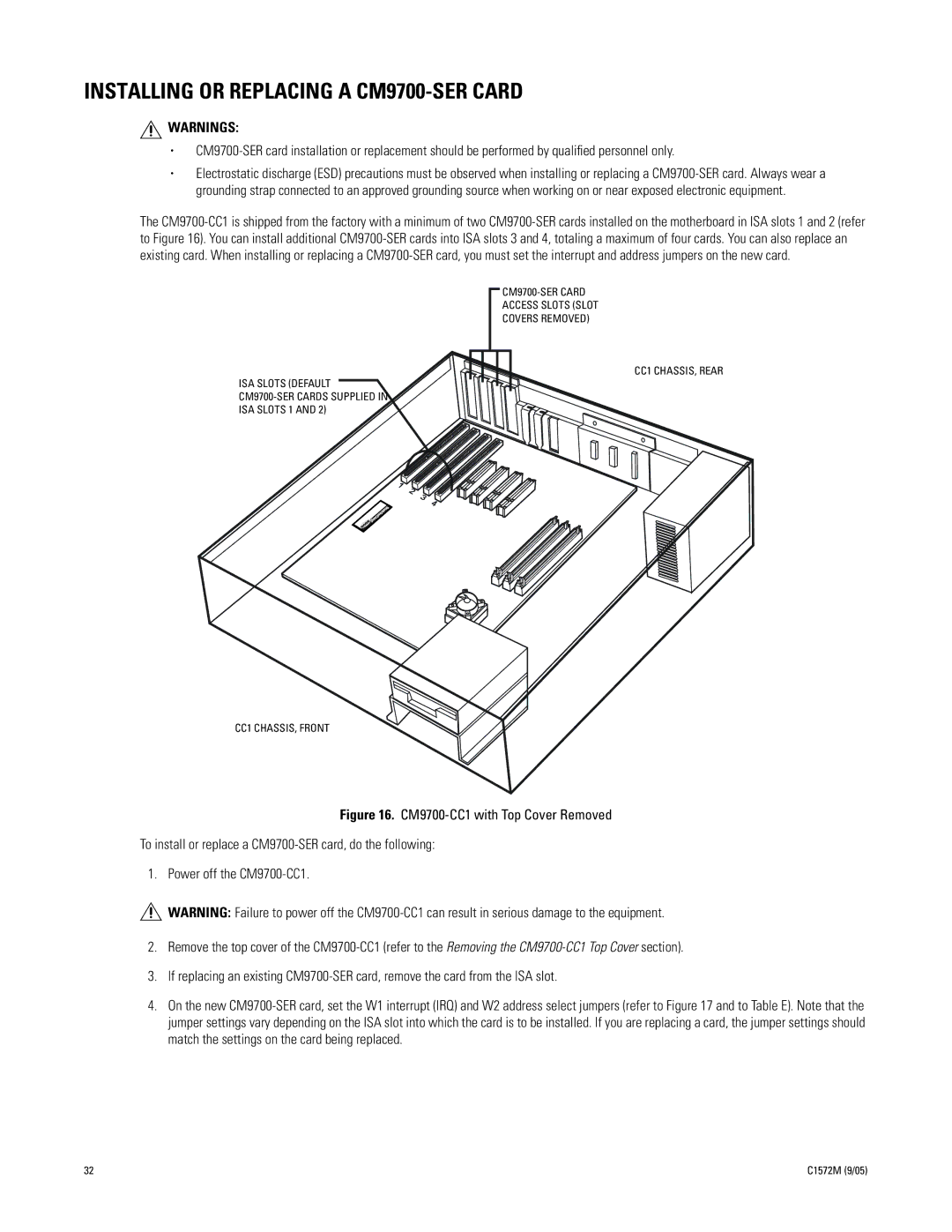
ACCESS SLOTS (SLOT
COVERS REMOVED)
ISA SLOTS (DEFAULT
CC1 CHASSIS, REAR
CC1 CHASSIS, FRONT
Figure 16. CM9700-CC1 with Top Cover Removed
To install or replace a CM9700-SER card, do the following:
1. Power off the CM9700-CC1.
WARNING: Failure to power off the
2.Remove the top cover of the CM9700-CC1 (refer to the Removing the CM9700-CC1 Top Cover section).
3.If replacing an existing CM9700-SER card, remove the card from the ISA slot.
4.On the new CM9700-SER card, set the W1 interrupt (IRQ) and W2 address select jumpers (refer to Figure 17 and to Table E). Note that the jumper settings vary depending on the ISA slot into which the card is to be installed. If you are replacing a card, the jumper settings should match the settings on the card being replaced.
32 | C1572M (9/05) |