Return to Section TOC
Return to Section TOC
Return to Section TOC
Return to Section TOC
Return to Master TOC
Return to Master TOC
Return to Master TOC
Return to Master TOC
THEORY OF OPERATION | |||
|
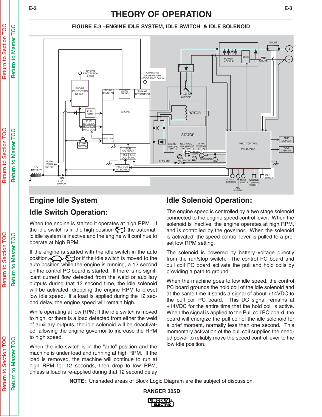
| FIGURE E.3 |
|
|
|
| SHUNT | + |
|
|
|
| |
POWER | IGBTs | CHOKE |
| - |
MODULE |
|
|
ENGINE |
|
| CHARGING |
|
PROTECTION |
|
|
| |
LIGHT |
|
| SYSTEM LIGHT |
|
|
|
| (CODE 10926 ONLY) |
|
ENGINE | ENGINE | GLOW | ENGINE |
|
PROTECTION | WELD | |||
CIRCUIT | SENSORS | PLUGS | ALTERNATOR | |
|
|
|
| WINDING |
|
|
|
|
|
|
|
|
|
|
|
|
|
|
|
|
|
|
|
|
|
|
| FUEL |
|
|
|
|
|
|
|
|
| ENGINE |
|
|
|
|
|
|
|
|
|
|
|
|
|
|
|
|
|
|
|
|
|
|
|
|
|
|
|
|
|
|
|
|
|
|
|
|
|
|
|
|
|
|
|
|
| ||||||
|
|
|
|
|
|
|
|
|
|
|
|
|
|
|
|
|
|
|
|
|
|
|
|
|
|
|
|
|
|
|
|
|
|
|
|
|
|
|
|
|
|
|
|
|
|
|
|
|
|
|
|
|
|
|
|
|
|
|
|
|
|
|
|
|
|
|
|
|
|
|
|
|
| |||||||||||
|
|
|
|
|
|
|
|
|
|
|
|
|
|
|
|
|
|
|
|
| PUMP |
|
|
|
|
|
|
|
|
|
|
|
|
|
|
|
|
|
|
|
|
|
|
|
|
|
|
|
|
|
| ROTOR |
|
|
|
|
|
|
|
|
|
|
|
|
|
|
|
|
|
|
|
|
|
|
|
| ||||||||
|
|
|
|
|
|
|
|
|
|
|
|
|
|
|
|
|
|
|
|
|
|
|
|
|
|
|
|
|
|
|
|
|
|
|
|
|
|
|
|
|
|
|
|
|
|
|
|
|
|
|
|
|
|
|
|
|
|
|
|
|
|
|
|
|
|
|
|
|
|
|
|
|
|
|
|
|
|
|
|
| ||||
|
|
|
|
|
|
|
|
|
|
|
|
|
|
|
|
|
|
|
|
| FUEL |
|
|
|
|
|
|
|
|
|
|
|
|
|
|
|
|
|
|
|
|
|
|
|
|
|
|
|
|
|
|
|
|
|
|
|
|
|
|
|
|
|
|
|
|
|
|
|
|
|
|
|
|
|
| |||||||||
|
|
|
|
|
|
|
|
|
|
|
|
|
|
|
|
|
|
|
| SOLENIOD |
|
|
|
|
|
|
|
|
|
|
|
|
|
|
|
|
|
|
|
|
|
|
|
|
|
|
|
|
|
|
|
|
|
|
|
|
|
|
|
|
|
|
|
|
|
|
|
|
|
|
|
|
|
|
|
|
|
|
| |||||
|
|
|
|
|
|
|
|
|
|
|
|
|
|
|
|
|
|
|
| HOLD COIL |
|
|
|
|
|
|
|
|
|
|
|
|
|
|
|
|
|
|
|
|
|
|
|
|
|
|
|
|
|
|
|
|
|
|
|
|
|
|
|
|
|
|
|
|
|
|
|
|
|
|
|
|
|
|
|
|
|
|
|
| ||||
|
|
|
|
|
|
|
|
|
|
|
|
|
|
|
|
|
|
|
| PULL COIL |
|
|
|
|
|
|
|
|
|
|
|
|
|
|
|
|
|
|
|
|
|
|
|
|
|
|
| STATOR |
|
|
|
|
|
|
|
|
|
|
|
|
|
|
|
|
|
|
|
|
|
|
|
|
| AMP |
| |||||||||
|
|
|
|
|
|
|
|
|
|
|
|
|
|
|
|
|
|
|
|
|
|
|
|
|
|
|
|
|
|
|
|
|
|
|
|
|
|
|
|
|
|
|
|
|
|
|
|
|
|
|
|
|
|
|
|
|
|
|
|
|
|
|
|
|
|
|
|
|
|
|
|
|
| |||||||||||
|
|
|
|
|
|
|
|
|
|
|
|
|
|
|
|
|
|
|
|
|
|
|
|
|
|
|
|
|
|
|
|
|
|
|
|
|
|
|
|
|
|
|
|
|
|
|
|
|
|
|
|
|
|
|
|
|
|
|
|
|
|
|
|
|
|
|
|
|
|
|
|
|
|
|
|
|
|
| ||||||
|
|
|
|
|
|
|
|
|
|
|
|
|
|
|
|
|
|
|
|
|
|
|
|
|
|
| STARTER |
|
|
|
|
|
|
|
|
|
|
|
|
|
|
|
|
|
|
|
|
|
|
|
|
|
|
|
|
|
|
|
|
|
|
|
|
|
|
|
|
|
|
|
|
|
|
| ||||||||||
|
|
|
|
|
|
|
|
|
|
|
|
|
|
|
|
|
| START |
|
|
|
|
|
|
|
|
|
|
|
|
|
|
|
|
|
|
|
|
|
|
|
|
|
|
| EXCITER |
| 120/240 VAC | 42 VAC |
|
|
|
|
|
|
|
| WELD CONTROL |
|
|
|
|
|
|
|
| DISPLAY |
| ||||||||||||||||
|
|
|
|
|
|
|
|
|
|
|
|
|
|
|
|
| BUTTON |
|
|
|
|
|
|
|
|
|
|
|
| IDLE |
|
|
|
|
|
|
|
| WINDING | AUX.WINDING | WINDING |
|
|
|
|
|
|
|
|
| P.C. BOARD |
|
|
|
|
|
|
|
| VOLT |
|
| ||||||||||||||||||||||
|
|
|
|
|
|
|
|
|
|
|
|
|
|
|
|
|
|
|
|
|
|
|
|
|
|
|
|
|
|
|
|
|
| SOLENOID |
|
|
|
|
|
|
|
|
|
|
|
|
|
|
|
| CURRENT |
|
|
|
|
|
|
|
|
|
|
|
|
|
|
|
|
|
|
|
|
|
|
| DISPLAY |
|
| |||||||
|
|
|
|
|
|
|
|
|
|
|
|
|
|
|
|
|
|
|
|
|
|
|
|
|
|
|
|
|
|
|
|
|
|
|
|
|
|
|
|
|
|
|
|
|
|
|
|
|
|
|
|
|
|
|
|
|
|
|
|
|
|
|
| |||||||||||||||||||||
|
|
|
|
|
|
|
|
|
|
|
|
|
|
|
|
|
|
|
|
|
|
|
|
|
|
|
|
|
|
|
|
|
|
|
|
|
|
|
|
|
|
|
|
|
|
|
|
|
|
|
|
|
|
|
|
|
|
|
|
|
|
|
|
|
|
|
|
|
|
|
| |||||||||||||
|
|
|
|
|
|
|
|
|
|
|
|
|
|
|
|
|
|
|
|
|
|
|
|
|
|
|
|
|
|
|
|
|
| PULL | HOLD |
|
|
|
|
|
|
|
|
|
|
|
|
| 240 |
|
| SENSOR 14 |
|
|
|
|
|
|
|
|
|
|
|
|
|
|
|
|
|
|
|
|
|
|
|
|
|
|
| |||||
|
|
|
|
|
|
|
|
|
|
|
|
|
|
|
|
|
|
|
|
|
|
|
|
|
|
|
|
|
|
|
|
|
| COIL | COIL |
|
|
|
|
|
|
|
|
|
|
|
|
| VAC |
|
| 120 | PIN |
| 6 |
|
|
|
|
|
|
|
|
|
|
|
|
|
|
|
|
|
|
|
|
| ||||||||
|
|
|
|
|
| GLOW |
|
|
|
|
|
|
|
|
|
|
|
|
|
|
|
|
|
|
|
|
|
|
|
|
|
|
|
|
|
|
|
|
|
| FLASHING |
| RECEPTACLES | vac | AMPHENALS PIN |
|
|
|
|
|
|
|
|
|
|
|
|
|
|
|
|
|
|
|
| |||||||||||||||||||
|
|
|
|
|
| PLUG |
|
|
|
|
|
|
|
|
|
|
|
|
|
|
|
|
|
|
|
|
|
|
|
|
|
|
|
|
|
|
|
|
|
|
|
|
|
|
|
|
|
|
|
|
|
|
|
|
|
|
|
|
|
|
|
|
|
|
|
|
|
|
|
|
|
|
|
|
|
|
|
|
|
|
|
|
|
|
|
|
| 12V. | BUTTON |
|
|
|
|
|
|
|
|
|
|
|
|
|
|
|
|
|
|
|
|
|
|
|
| PULL COIL |
|
|
|
|
|
|
|
|
|
|
|
|
|
|
|
|
|
|
|
|
|
|
|
|
|
|
|
|
|
|
|
|
|
|
|
|
|
|
|
|
|
|
|
|
|
|
|
|
|
| |||||
|
| BATTERY |
|
|
|
|
|
|
|
|
|
|
|
|
|
|
|
|
|
|
|
|
|
| PC BOARD |
|
|
|
|
|
|
|
|
|
|
|
|
|
|
|
|
|
|
|
|
|
|
|
|
|
|
|
|
|
|
|
|
|
|
|
|
|
|
|
|
| IDLE |
|
|
|
|
|
| |||||||||||
|
|
|
|
|
|
|
|
|
|
|
|
|
|
|
|
|
|
|
|
|
|
|
|
|
|
|
|
|
|
|
|
|
|
|
|
|
|
|
|
|
|
|
|
|
|
|
|
|
|
|
|
|
|
|
|
|
|
|
|
|
|
|
|
|
|
|
|
|
|
|
|
|
|
|
|
|
|
|
|
|
| |||
|
|
|
|
|
|
|
|
| RUN |
|
|
|
|
|
|
|
|
|
|
|
|
|
|
|
|
|
|
|
|
|
|
|
|
|
|
|
|
|
|
|
|
|
|
|
|
|
|
|
|
|
|
|
|
|
|
|
|
|
|
|
|
|
| OUTPUT |
| MODE | WELDING |
|
| SWITCH |
|
|
|
|
|
| ||||||||
|
|
|
|
|
|
|
|
| STOP |
|
|
|
|
|
|
|
|
|
|
|
|
|
|
|
|
|
|
|
|
|
|
|
|
|
|
|
|
|
|
|
|
|
|
|
|
|
|
|
|
|
|
|
|
|
|
|
|
|
|
|
|
|
|
|
|
|
|
|
|
|
|
|
|
|
| |||||||||
|
|
|
|
|
|
| SWITCH |
|
|
|
|
|
|
|
|
|
|
|
|
|
|
|
|
|
|
|
|
|
|
|
|
|
|
|
|
|
|
|
|
|
|
|
|
|
|
|
|
|
|
|
|
|
|
|
|
|
|
|
|
|
| CONTROL |
| SWITCH | TERMINAL |
|
|
|
|
|
|
|
|
|
|
| ||||||||
Engine Idle System |
|
|
|
|
|
|
|
|
|
|
|
|
|
|
|
|
|
|
|
|
|
|
|
|
|
|
|
|
|
|
|
|
|
|
|
|
| ARC |
|
| SWITCH |
|
|
|
|
|
|
|
|
|
|
| ||||||||||||||||||||||||||||||||
|
|
|
|
|
|
|
|
|
|
|
|
|
|
|
|
|
|
|
|
|
|
|
|
|
|
|
|
|
|
|
|
|
|
|
|
| CONTROL |
|
|
|
|
|
|
|
|
|
|
|
|
| ||||||||||||||||||||||||||||||||||
|
|
|
|
|
|
|
|
|
|
|
|
|
|
|
| Idle Solenoid Operation: |
|
|
|
|
|
|
|
|
|
|
| |||||||||||||||||||||||||||||||||||||||||||||||||||||||||
Idle Switch Operation: |
|
|
|
|
|
|
|
|
|
|
|
|
|
|
|
| The engine speed is controlled by a two stage solenoid | |||||||||||||||||||||||||||||||||||||||||||||||||||||||||||||||||||
|
|
|
|
|
|
|
|
|
|
|
|
|
|
|
| connected to the engine speed control lever. When the | ||||||||||||||||||||||||||||||||||||||||||||||||||||||||||||||||||||
When the engine is started it operates at high RPM. If |
|
|
| solenoid is inactive, the engine operates at high RPM, | ||||||||||||||||||||||||||||||||||||||||||||||||||||||||||||||||||||||||||||||||
the idle switch is in the high position |
|
|
| the automat- |
|
|
| and is controlled by the governor. | When the solenoid | |||||||||||||||||||||||||||||||||||||||||||||||||||||||||||||||||||||||||||
ic idle system is inactive and the engine will continue to |
|
|
| is activated, the speed control lever is pulled to a pre- | ||||||||||||||||||||||||||||||||||||||||||||||||||||||||||||||||||||||||||||||||
operate at high RPM. |
|
|
|
|
|
|
|
|
|
|
|
|
|
|
|
|
|
|
|
|
|
|
|
|
|
| set low RPM setting. |
|
|
|
|
|
|
|
|
|
|
|
|
|
|
|
|
|
|
|
| |||||||||||||||||||||||||||||||||||||
If the engine is started with the idle switch in the auto |
|
|
| The solenoid is powered by battery voltage directly | ||||||||||||||||||||||||||||||||||||||||||||||||||||||||||||||||||||||||||||||||
position, |
|
|
|
| or if the idle switch is moved to the |
|
|
| from the run/stop switch. |
|
| The control PC board and | ||||||||||||||||||||||||||||||||||||||||||||||||||||||||||||||||||||||||
auto position while the engine is running, a 12 second |
|
|
| pull coil PC board activate the pull and hold coils by | ||||||||||||||||||||||||||||||||||||||||||||||||||||||||||||||||||||||||||||||||
on the control PC board is started. If there is no signif- |
|
|
| providing a path to ground. |
|
|
|
|
|
|
|
|
|
|
|
|
|
|
| |||||||||||||||||||||||||||||||||||||||||||||||||||||||||||||||||
icant current flow detected from the weld or auxiliary |
|
|
| When the machine goes to low idle speed, the control | ||||||||||||||||||||||||||||||||||||||||||||||||||||||||||||||||||||||||||||||||
outputs during that 12 second time, the idle solenoid |
|
|
| PC board grounds the hold coil of the idle solenoid and | ||||||||||||||||||||||||||||||||||||||||||||||||||||||||||||||||||||||||||||||||
will be activated, dropping the engine RPM to preset |
|
|
| at the same time it sends a signal of about +14VDC to | ||||||||||||||||||||||||||||||||||||||||||||||||||||||||||||||||||||||||||||||||
low idle speed. If a load is applied during the 12 sec- |
|
|
| the pull | coil | PC | board. |
| This | DC | signal remains at | |||||||||||||||||||||||||||||||||||||||||||||||||||||||||||||||||||||||||
ond delay, the engine speed will remain high. |
|
|
| +14VDC for the entire time that the hold coil is active. | ||||||||||||||||||||||||||||||||||||||||||||||||||||||||||||||||||||||||||||||||
While operating at low RPM; if the idle switch is moved |
|
|
| When the signal is applied to the Pull coil PC board, the | ||||||||||||||||||||||||||||||||||||||||||||||||||||||||||||||||||||||||||||||||
to high, or there is a load detected from either the weld |
|
|
| board will energize the pull coil of the idle solenoid for | ||||||||||||||||||||||||||||||||||||||||||||||||||||||||||||||||||||||||||||||||
of auxiliary outputs, the idle solenoid will be deactivat- |
|
|
| a brief moment, normally less than one second. | This | |||||||||||||||||||||||||||||||||||||||||||||||||||||||||||||||||||||||||||||||
ed, allowing the engine governor to increase the RPM |
|
|
| momentary activation of the pull coil supplies the need- | ||||||||||||||||||||||||||||||||||||||||||||||||||||||||||||||||||||||||||||||||
to high speed. |
|
|
|
|
|
|
|
|
|
|
|
|
|
|
|
|
|
|
|
|
|
|
|
|
|
|
|
|
|
|
|
|
|
|
|
| ed power to reliably move the speed control lever to the | |||||||||||||||||||||||||||||||||||||||||||||||
When the idle switch is in the “auto” position and the |
|
|
| low idle position. |
|
|
|
|
|
|
|
|
|
|
|
|
|
|
|
|
|
|
|
|
|
|
|
| ||||||||||||||||||||||||||||||||||||||||||||||||||||||||
machine is under load and running at high RPM. If the |
|
|
|
|
|
|
|
|
|
|
|
|
|
|
|
|
|
|
|
|
|
|
|
|
|
|
|
|
|
|
|
|
|
|
|
|
|
|
|
|
| |||||||||||||||||||||||||||||||||||||||||||
load is removed, the machine will continue to run at |
|
|
|
|
|
|
|
|
|
|
|
|
|
|
|
|
|
|
|
|
|
|
|
|
|
|
|
|
|
|
|
|
|
|
|
|
|
|
|
|
| |||||||||||||||||||||||||||||||||||||||||||
high RPM for 12 seconds, then drop to low RPM, |
|
|
|
|
|
|
|
|
|
|
|
|
|
|
|
|
|
|
|
|
|
|
|
|
|
|
|
|
|
|
|
|
|
|
|
|
|
|
|
|
| |||||||||||||||||||||||||||||||||||||||||||
unless a load is |
|
|
|
|
|
|
|
|
|
|
|
|
|
|
|
|
|
|
|
|
|
|
|
|
|
|
|
|
|
|
|
|
|
|
|
|
|
|
|
|
| |||||||||||||||||||||||||||||||||||||||||||
|
|
|
|
|
|
|
|
|
|
|
| NOTE: |
|
| Unshaded areas of Block Logic Diagram are the subject of discussion. |
|
|
|
|
|
|
|
|
|
|
| ||||||||||||||||||||||||||||||||||||||||||||||||||||||||||
|
|
|
|
|
|
|
|
|
|
|
|
|
|
|
|
|
|
|
|
|
|
|
|
|
|
|
|
|
|
|
|
|
|
|
|
|
|
| RANGER 305D |
|
|
|
|
|
|
|
|
|
|
|
|
|
|
|
|
|
|
|
|
|
|
|
|
|
|
|
|
|
| |||||||||||||||