Return to Section TOC
Return to Master TOC
| THEORY OF OPERATION |
| ||||||||||
|
|
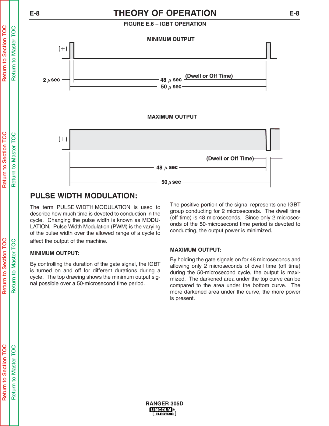
| FIGURE E.6 – IGBT OPERATION |
|
| |||||||
|
|
|
|
|
|
|
|
|
|
|
|
|
|
|
|
|
|
|
|
|
|
|
|
|
|
|
|
|
|
|
|
|
|
|
|
|
|
|
|
|
|
|
|
|
|
|
|
|
|
|
|
|
|
|
|
|
|
|
|
|
|
|
|
|
|
|
|
|
|
|
|
|
|
|
|
|
|
|
|
|
|
|
|
|
|
|
|
|
|
|
|
|
|
|
|
|
|
|
|
|
|
|
|
|
|
|
|
|
|
|
|
|
|
|
|
|
|
|
|
|
|
|
|
|
|
|
|
|
|
|
|
|
|
|
|
|
|
|
|
|
|
|
|
|
|
|
|
|
|
|
|
|
|
|
|
|
|
|
|
|
|
|
|
|
|
|
|
|
Return to Section TOC
Return to Section TOC
Return to Master TOC
Return to Master TOC
PULSE WIDTH MODULATION:
The term PULSE WIDTH MODULATION is used to describe how much time is devoted to conduction in the cycle. Changing the pulse width is known as MODU- LATION. Pulse Width Modulation (PWM) is the varying of the pulse width over the allowed range of a cycle to affect the output of the machine.
MINIMUM OUTPUT:
By controlling the duration of the gate signal, the IGBT is turned on and off for different durations during a cycle. The top drawing shows the minimum output sig- nal possible over a
The positive portion of the signal represents one IGBT group conducting for 2 microseconds. The dwell time (off time) is 48 microseconds. Since only 2 microsec- onds of the
MAXIMUM OUTPUT:
By holding the gate signals on for 48 microseconds and allowing only 2 microseconds of dwell time (off time) during the
Return to Section TOC
Return to Master TOC