Return to Section TOC
Return to Section TOC
Return to Section TOC
Return to Section TOC
Return to Master TOC
Return to Master TOC
Return to Master TOC
Return to Master TOC
TROUBLESHOOTING & REPAIR | ||||||||||||||||
| CHOPPER MODULE REMOVAL AND REPLACEMENT (continued) | |||||||||||||||
|
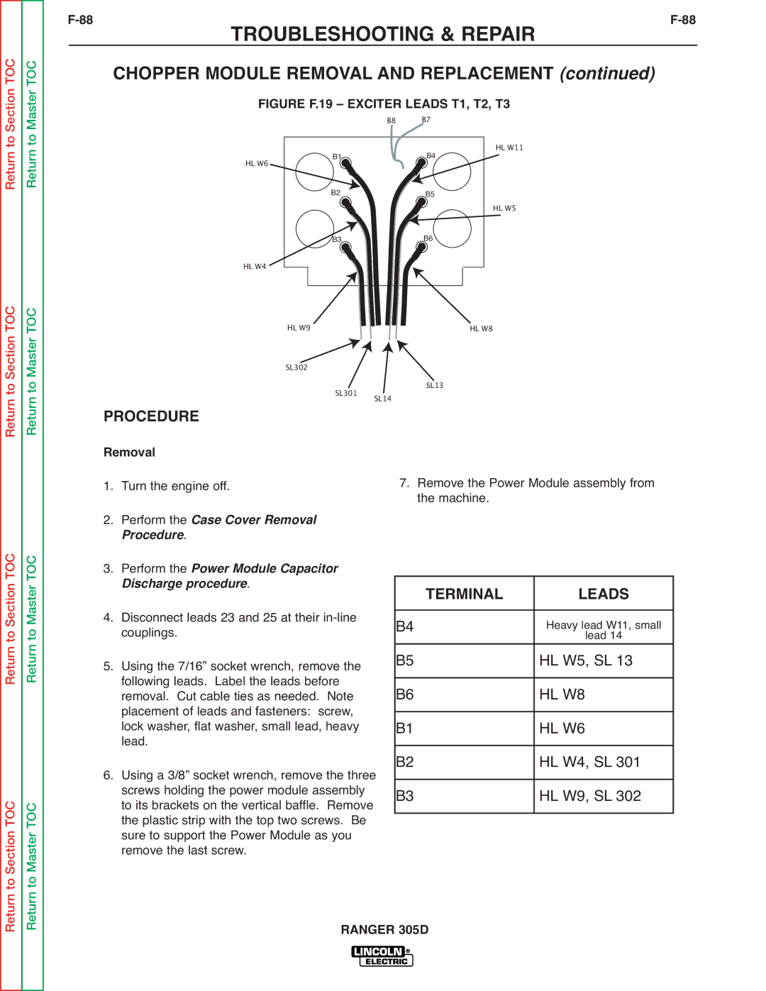
| FIGURE F.19 – EXCITER LEADS T1, T2, T3 |
|
| ||||||||||||
|
|
|
|
|
|
|
| B8 | B7 | HL W11 |
|
| ||||
|
| HL W6 |
|
|
| B1 |
|
|
| B4 |
|
|
| |||
|
|
|
| B2 |
|
|
|
|
|
|
|
|
|
| ||
|
|
|
|
|
|
|
|
| B5 |
| HL W5 |
|
| |||
|
|
|
|
|
|
|
|
|
|
|
|
|
|
| ||
|
|
|
|
|
| B3 |
|
|
| B6 |
|
|
|
|
| |
|
| HL W4 |
|
|
|
|
|
|
|
|
|
|
|
|
|
|
|
|
|
|
|
|
|
|
|
|
|
|
|
|
|
| |
|
|
|
|
|
|
|
|
|
|
|
|
|
|
| ||
|
|
| HL W9 |
|
|
|
|
| HL W8 |
|
|
|
| |||
|
|
| SL302 | SL301 |
|
|
| SL13 |
|
|
|
| ||||
| PROCEDURE | SL14 |
|
|
|
| ||||||||||
|
|
|
|
|
|
|
| |||||||||
|
|
|
|
|
|
|
|
|
|
|
| |||||
| Removal |
|
| 7. | Remove the Power Module assembly from | |||||||||||
1. | Turn the engine off. |
|
| |||||||||||||
| 2. Perform the Case Cover Removal |
|
|
|
| the machine. |
|
|
|
| ||||||
|
| Procedure. |
|
|
|
|
|
|
|
|
|
|
| |||
| 3. Perform the Power Module Capacitor |
|
|
|
|
|
|
|
|
|
| |||||
|
| Discharge procedure. |
|
|
|
| TERMINAL |
| LEADS |
| ||||||
|
|
|
|
|
|
|
| |||||||||
4. | Disconnect leads 23 and 25 at their |
|
|
|
|
|
|
|
|
|
| |||||
|
| B4 |
|
|
|
|
| Heavy lead W11, small |
| |||||||
|
| couplings. |
|
|
|
|
|
|
|
| lead 14 |
| ||||
5. | Using the 7/16” socket wrench, remove the |
|
| B5 |
|
|
|
|
| HL W5, SL 13 |
| |||||
|
| following leads. Label the leads before |
|
|
|
|
|
|
|
|
|
| ||||
|
|
|
| B6 |
|
|
|
|
| HL W8 |
| |||||
|
| removal. Cut cable ties as needed. Note |
|
|
|
|
|
|
|
| ||||||
|
| placement of leads and fasteners: screw, |
|
|
|
|
|
|
|
|
|
| ||||
|
|
|
| B1 |
|
|
|
|
| HL W6 |
| |||||
|
| lead. |
|
|
|
|
|
|
|
|
| |||||
|
| lock washer, flat washer, small lead, heavy |
|
| B2 |
|
|
|
|
| HL W4, SL 301 |
| ||||
6. | Using a 3/8” socket wrench, remove the three |
|
|
|
|
|
|
| ||||||||
|
| screws holding the power module assembly |
|
| B3 |
|
|
|
|
| HL W9, SL 302 |
| ||||
|
| to its brackets on the vertical baffle. Remove |
|
|
|
|
|
|
|
| ||||||
|
| the plastic strip with the top two screws. Be |
|
|
|
|
|
|
|
|
|
| ||||
|
|
|
|
|
|
|
|
|
|
|
| |||||
|
| sure to support the Power Module as you |
|
|
|
|
|
|
|
|
|
| ||||
|
| remove the last screw. |
|
|
|
|
|
|
|
|
|
|
| |||
|
|
|
|
|
| RANGER 305D |
|
|
|
| ||||||