Return to Section TOC
Return to Section TOC
Return to Section TOC
Return to Section TOC
Return to Master TOC
Return to Master TOC
Return to Master TOC
Return to Master TOC
OPERATION | |||
The 240 VAC receptacle can be split to provide two | NOTE: The 240 VAC receptacle has two circuits, each | ||
separate120 VAC outputs with a maximum permissible | of which measure 120 VAC to neutral. However, they | ||
current of 42 amps pea, 40 amps continuous per out- | are of opposite polarities and cannot be paralleled. | ||
let to two separate 20 amp branch circuits. (These cir- | |||
cuits cannot be paralleled.) | Output voltage is within +/- | SIMULTANEOUS WELDING AND |
|
10% at all loads up to rated capacity. | AUXILIARY POWER LOADS |
| |
The 120 V auxiliary power receptacles should only be | The above auxiliary power ratings are with no welding | ||
load. Simultaneous welding and power loads are spec- | |||
used with | ified in Table B.4. The permissible currents shown | ||
double insulated tools with | assume that current is being drawn from either the 120 | ||
rating of any plug used with the system must be at | VAC or 240 VAC supply (not both at the same time). | ||
least equal to the current capacity of the associated |
|
| |
receptacle. For extension cord lengths, see Table B.5. |
|
| |
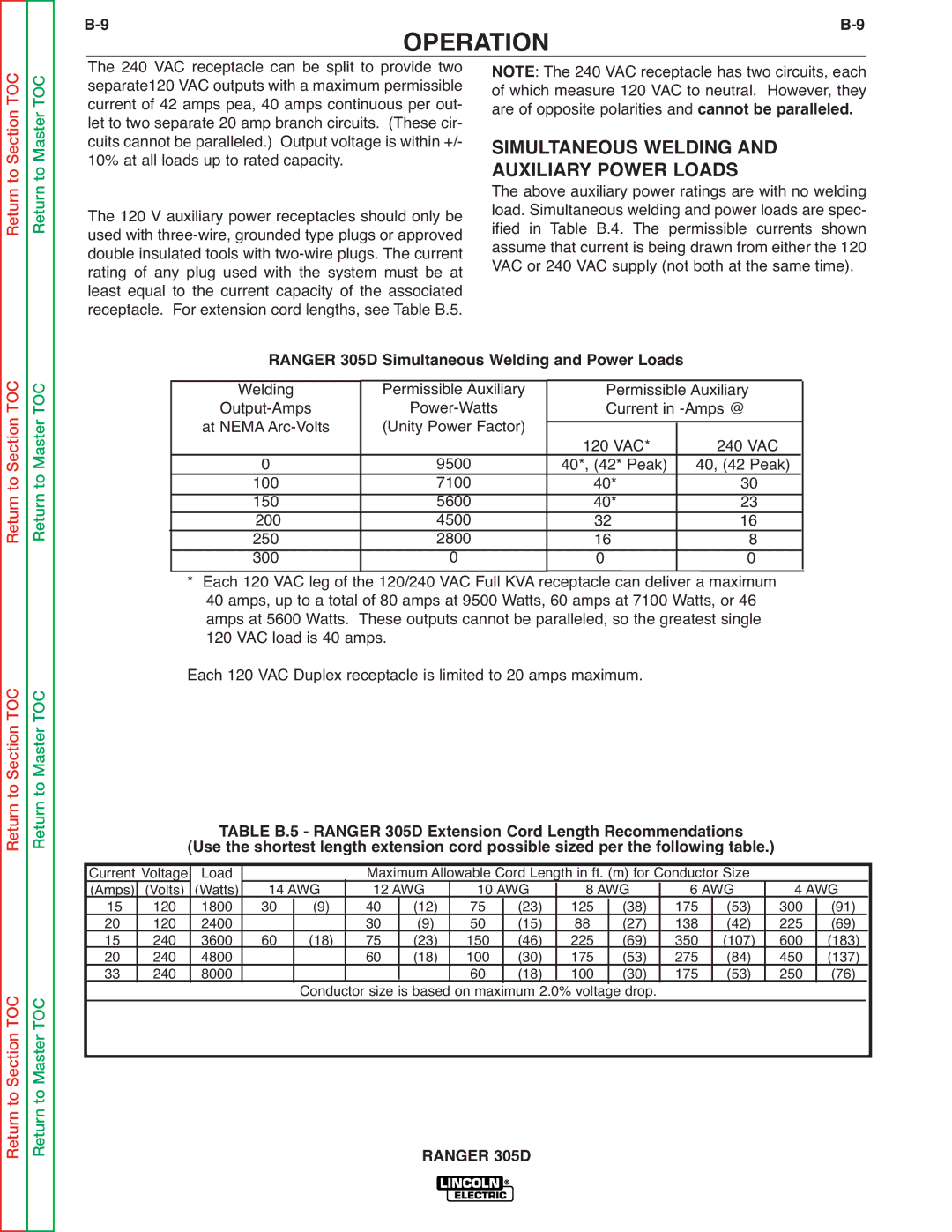
RANGER 305D Simultaneous Welding and Power Loads |
|
| |||
Welding | Permissible Auxiliary |
| Permissible Auxiliary |
| |
|
| ||||
| Current in |
| |||
at NEMA | (Unity Power Factor) |
|
|
|
|
| 120 VAC* | 240 VAC |
| ||
0 | 9500 |
| 40*, (42* Peak) | 40, (42 Peak) |
|
100 | 7100 |
| 40* | 30 |
|
150 | 5600 |
| 40* | 23 |
|
200 | 4500 |
| 32 | 16 |
|
250 | 2800 |
| 16 | 8 |
|
300 | 0 |
| 0 | 0 |
|
* Each 120 VAC leg of the 120/240 VAC Full KVA |
| receptacle can deliver a maximum |
| ||
|
| ||||
40 amps, up to a total of 80 amps at 9500 Watts, 60 amps at 7100 Watts, or 46 | |||||
amps at 5600 Watts. These outputs cannot be paralleled, so the greatest single | |||||
120 VAC load is 40 amps. |
|
|
|
| |
Each 120 VAC Duplex receptacle is limited to 20 amps maximum. |
|
| |||
|
| TABLE B.5 - RANGER 305D Extension Cord Length Recommendations |
|
| ||||||||||
| (Use the shortest length extension cord possible sized per the following table.) |
|
| |||||||||||
Current Voltage | Load | 14 AWG | Maximum Allowable Cord Length in ft. (m) for Conductor Size | 4 AWG | ||||||||||
(Amps) | (Volts) | (Watts) | 12 AWG | 10 AWG | 8 AWG | 6 AWG | ||||||||
15 | 120 | 1800 | 30 | (9) | 40 | (12) | 75 | (23) | 125 | (38) | 175 | (53) | 300 | (91) |
20 | 120 | 2400 | 60 | (18) | 30 | (9) | 50 | (15) | 88 | (27) | 138 | (42) | 225 | (69) |
15 | 240 | 3600 | 75 | (23) | 150 | (46) | 225 | (69) | 350 | (107) | 600 | (183) | ||
20 | 240 | 4800 |
|
| 60 | (18) | 100 | (30) | 175 | (53) | 275 | (84) | 450 | (137) |
33 | 240 | 8000 |
|
|
|
| 60 | (18) | 100 | (30) | 175 | (53) | 250 | (76) |
|
|
|
| Conductor size is based on maximum 2.0% voltage drop. |
|
|
|
| ||||||
RANGER 305D