Return to Section TOC
Return to Section TOC
Return to Section TOC
Return to Section TOC
Return to Master TOC
Return to Master TOC
Return to Master TOC
Return to Master TOC
| TROUBLESHOOTING & REPAIR | ||||||||||||
|
| CHOPPER MODULE FUNCTION TEST (continued) | |||||||||||
|
|
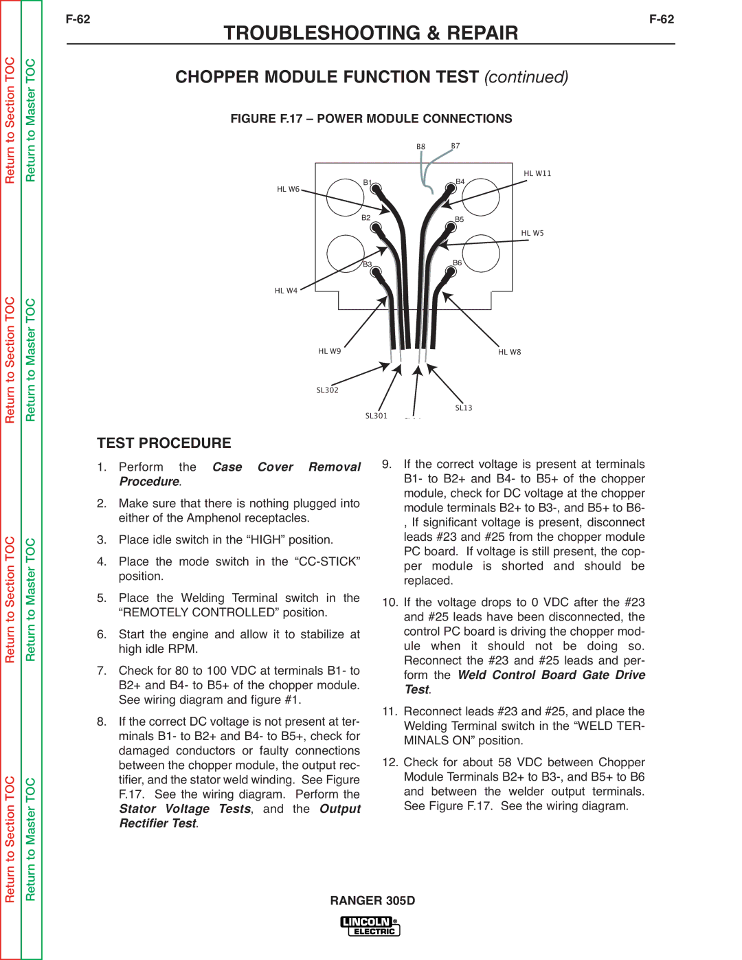
| FIGURE F.17 – POWER MODULE CONNECTIONS |
| |||||||||
|
|
|
|
|
|
|
| B8 |
| B7 | HL W11 | ||
|
|
| HL W6 |
|
|
| B1 |
|
| B4 |
| ||
|
|
|
|
| B2 |
|
|
|
|
|
| ||
|
|
|
|
|
|
|
|
| B5 |
| HL W5 | ||
|
|
|
|
|
|
|
|
|
|
|
|
| |
|
|
|
|
|
|
| B3 |
|
| B6 |
|
| |
|
|
| HL W4 |
|
|
|
|
|
|
|
|
|
|
|
|
|
|
|
|
|
|
|
|
|
|
| |
|
|
|
|
|
|
|
|
|
|
|
| ||
|
|
|
| HL W9 |
|
|
|
| HL W8 |
| |||
|
|
|
| SL302 | SL301 |
|
| SL13 |
| ||||
| TEST PROCEDURE | SL14 |
|
| |||||||||
|
|
|
|
|
| ||||||||
| 9. | If the correct voltage is present at terminals | |||||||||||
1. | Perform the | Case Cover Removal | |||||||||||
|
| Proced . |
|
|
|
|
| B1- to B2+ and B4- to B5+ of the chopper | |||||
2. | Make sure that there is nothing plugged into |
| module, check for DC voltage at the chopper | ||||||||||
| module terminals B2+ to | ||||||||||||
3. | either of the Amphenol receptacles. |
| , If significant voltage is present, disconnect | ||||||||||
Place idle switch in the “HIGH” position. |
| leads #23 and #25 from the chopper module | |||||||||||
4. | Place the mode switch in the |
| PC board. If voltage is still present, the cop- | ||||||||||
| per module is shorted and should be | ||||||||||||
5. | position. |
|
|
|
| 10. | replaced. |
| |||||
Place the Welding Terminal switch in the | If the voltage drops to 0 VDC after the #23 | ||||||||||||
6. | “REMOTELY CONTROLLED” position. |
| and #25 leads have been disconnected, the | ||||||||||
Start the engine and allow it to stabilize at |
| control PC board is driving the chopper mod- | |||||||||||
|
| high idle RPM. |
|
|
|
|
| ule when it should not be doing so. | |||||
|
|
|
|
|
|
| Reconnect the #23 and #25 leads and per- | ||||||
| 7. Check for 80 to 100 VDC at terminals B1- to |
| form the | Weld Control Board Gate Drive | |||||||||
|
| B2+ and B4- to B5+ of the chopper module. |
| T st | . |
|
|
|
| ||||
8. | See wiring diagram and figure #1. | 11. |
|
|
|
|
| ||||||
If the correct DC voltage is not present at ter- | Reconnect leads #23 and #25, and place the | ||||||||||||
|
| minals B1- to B2+ and B4- to B5+, check for |
| Welding Terminal switch in the “WELD TER- | |||||||||
|
| damaged conductors or faulty connections | 12. | MINALS ON” position. | |||||||||
|
| between the chopper module, the output rec- | Check for about 58 VDC between Chopper | ||||||||||
|
| tifier, and the stator weld winding. See Figure |
| Module Terminals B2+ to | |||||||||
|
| F.17. See the wiring diagram. Perform the |
| and between the welder output terminals. | |||||||||
|
| Stator Voltage Tests, and the Output |
| See Figure F.17. See the wiring diagram. | |||||||||
|
| Rectifier Test. |
|
|
|
|
|
|
|
|
|
|
|