Return to Section TOC
Return to Section TOC
Return to Master TOC
Return to Master TOC
F-34 TROUBLESHOOTING & REPAIRF-34
IDLER SOLENOID TEST (continued)
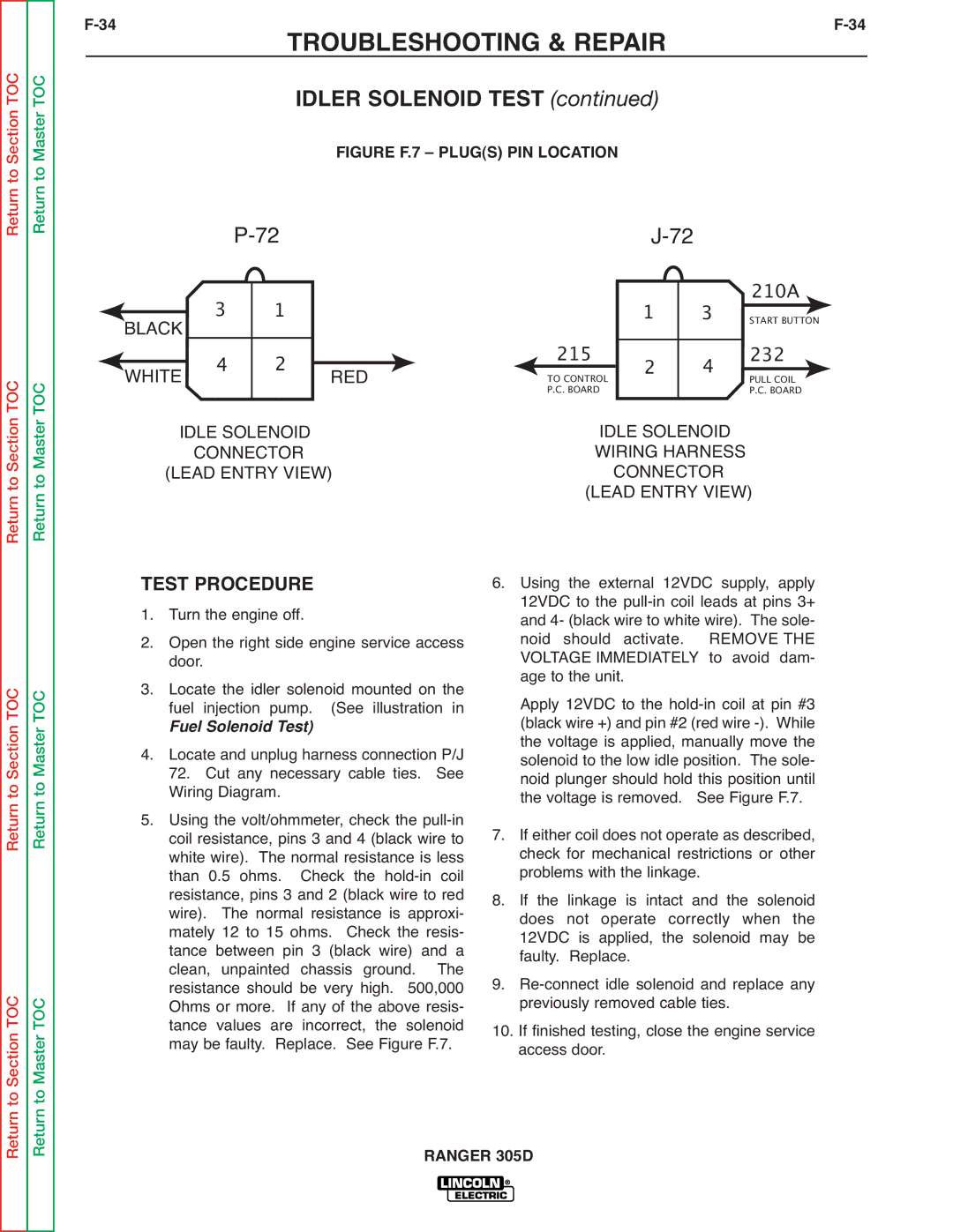
FIGURE F.7 – PLUG(S) PIN LOCATION
|
|
|
|
|
|
|
|
|
| 210A | ||||||
BLACK | 3 |
| 1 |
|
|
|
| 1 |
| 3 |
|
| ||||
|
|
|
|
|
|
|
| |||||||||
|
|
| 215 |
|
|
| START BUTTON |
| ||||||||
|
|
|
|
|
|
|
|
|
|
|
| 232 |
|
| ||
WHITE | 4 |
| 2 |
|
| 2 |
| 4 |
|
| ||||||
|
| RED |
| TO CONTROL |
|
|
|
|
|
| ||||||
|
|
|
|
| PULL COIL | |||||||||||
|
|
|
|
|
| P.C. BOARD |
|
|
| P.C. BOARD | ||||||
IDLE SOLENOID |
|
|
| IDLE SOLENOID |
|
|
| |||||||||
| CONNECTOR |
|
|
| WIRING HARNESS |
|
|
| ||||||||
(LEAD ENTRY VIEW) |
|
| CONNECTOR |
|
|
| ||||||||||
|
|
|
|
|
|
| (LEAD ENTRY VIEW) | |||||||||
Return to Section TOC
to Section TOC
Return to Master TOC
to Master TOC
TEST PROCEDURE 1. Turn the engine off.
2. Open the right side engine service access door.
3. Locate the idler solenoid mounted on the fuel injection pump. (See illustration in
Fuel Solenoid Test)
4. Locate and unplug harness connection P/J
72. Cut any necessary cable ties. See Wiring Diagram.
5. Using the volt/ohmmeter, check the
6.Using the external 12VDC supply, apply 12VDC to the
Apply 12VDC to the
7.If either coil does not operate as described, check for mechanical restrictions or other problems with the linkage.
8.If the linkage is intact and the solenoid does not operate correctly when the 12VDC is applied, the solenoid may be faulty. Replace.
9.
10.If finished testing, close the engine service access door.
Return
Return