Return to Section TOC
Return to Section TOC
Return to Section TOC
Return to Section TOC
Return to Master TOC
Return to Master TOC
Return to Master TOC
Return to Master TOC
|
|
|
|
|
|
|
|
|
| ||
TROUBLESHOOTING & REPAIR |
|
|
|
|
|
| |||||
Observe Safety Guidelines |
|
|
|
|
|
| |||||
detailed in the beginning of this manual. |
|
| TROUBLESHOOTING GUIDE | ||||||||
PROBLEMS |
| POSSIBLE AREAS OF |
| RECOMMENDED |
|
|
| ||||
|
|
|
|
| |||||||
(SYMPTOMS) |
| MISADJUSTMENT(S) |
| COURSE OF ACTION |
| ||||||
|
| WELD OUTPUT PROBLEMS |
|
|
|
|
|
|
| ||
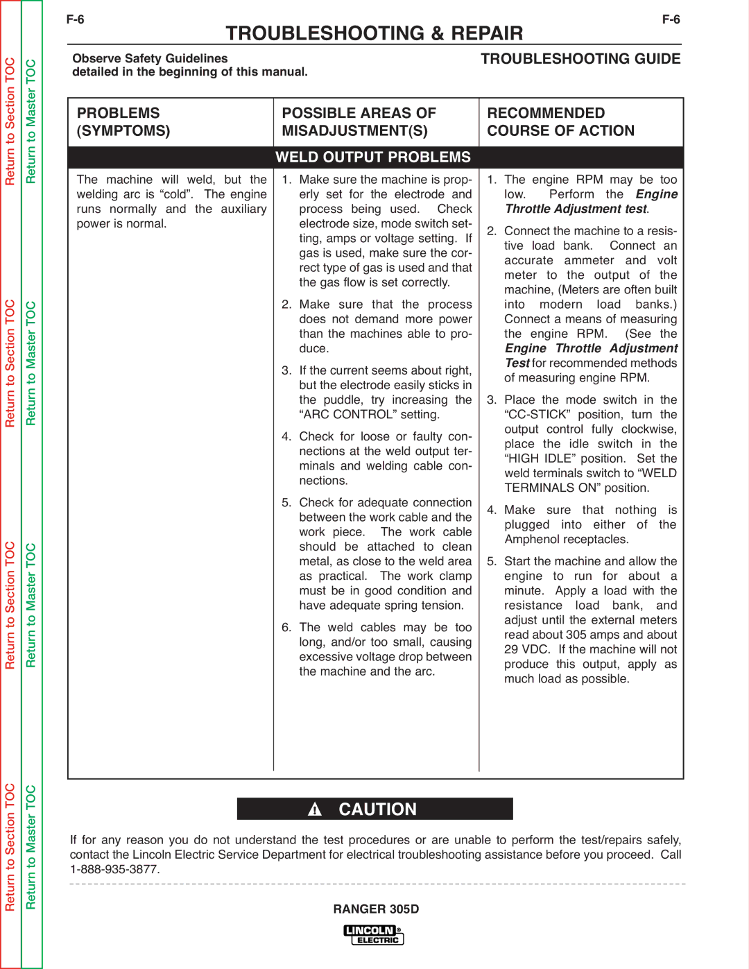
The machine will weld, but the |
| 1. Make sure the machine is prop- | 1. The engine RPM may be too | ||||||||
welding arc is “cold”. The engine |
| erly set for the electrode and | low. | Perform | the | Engine | |||||
runs normally and the auxiliary |
| process being used. | Check | Throttle Adjustment test. |
| ||||||
power is normal. |
| electrode size, mode switch set- | 2. Connect the machine to a resis- | ||||||||
|
| ting, amps or voltage setting. If | tive | load | bank. | Connect | an | ||||
|
| gas is used, make sure the cor- | accurate | ammeter | and | volt | |||||
|
| rect type of gas is used and that | meter to the output of the | ||||||||
|
| the gas flow is set correctly. | machine, (Meters are often built | ||||||||
|
| 2. Make sure that the process | into | modern | load | banks.) | |||||
|
| does not demand more power | Connect a means of measuring | ||||||||
|
| than the machines able to pro- | the | engine RPM. | (See | the | |||||
|
| 3. If the current seems about right, | Test for recommended methods | ||||||||
|
| duce. |
|
| Engine Throttle | Adjustment | |||||
|
| but the electrode easily sticks in | of measuring engine RPM. |
| |||||||
|
| the puddle, try increasing the | 3. Place the mode switch in the | ||||||||
|
| “ARC CONTROL” setting. | |||||||||
|
| 4. Check for loose or faulty con- | output control | fully clockwise, | |||||||
|
| place the idle switch in the | |||||||||
|
| nections at the weld output ter- | “HIGH IDLE” position. Set the | ||||||||
|
| minals and welding cable con- | weld terminals switch to “WELD | ||||||||
|
| nections. |
|
| TERMINALS ON” position. |
| |||||
|
| 5. Check for adequate connection | 4. Make sure that nothing is | ||||||||
|
| between the work cable and the | |||||||||
|
| work piece. | The work | cable | plugged into either of the | ||||||
|
| should be attached to clean | Amphenol receptacles. |
| |||||||
|
| metal, as close to the weld area | 5. Start the machine and allow the | ||||||||
|
| as practical. | The work clamp | engine to run for about a | |||||||
|
| must be in good condition and | minute. Apply a load with the | ||||||||
|
| have adequate spring tension. | resistance | load | bank, | and | |||||
|
| 6. The weld cables may be too | adjust until the external meters | ||||||||
|
| read about 305 amps and about | |||||||||
|
| long, and/or too small, causing | 29 VDC. If the machine will not | ||||||||
|
| excessive voltage drop between | produce this output, apply as | ||||||||
|
| the machine and the arc. |
| much load as possible. |
| ||||||
|
|
|
|
|
|
|
|
|
|
|
|
CAUTION
If for any reason you do not understand the test procedures or are unable to perform the test/repairs safely, contact the Lincoln Electric Service Department for electrical troubleshooting assistance before you proceed. Call
