Return to Section TOC
Return to Section TOC
Return to Section TOC
Return to Section TOC
Return to Master TOC
Return to Master TOC
Return to Master TOC
Return to Master TOC
OPERATION |
| ||
| FIGURE B.1 |
|
|
| NOTE: Layout and appearance |
|
|
| 6 vary between models. | 8 4 |
|
| 5 | 7 |
|
| 1 | 3 |
|
9 | 2 | 16 | |
10 |
|
11![]()
![]()
![]()
![]()
![]()
![]()
![]()
![]() 14 15
14 15 ![]()
![]()
![]()
![]()
![]()
![]()
![]() 12 13
12 13
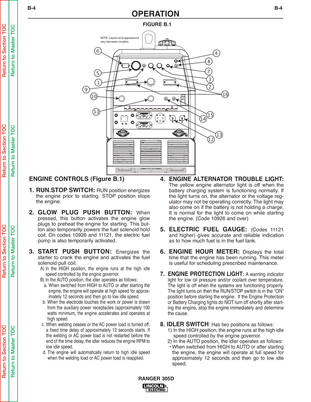
ENGINE CONTROLS (Figure B.1) ![]()
![]() 1. RUN.STOP SWITCH: RUN position energizes
1. RUN.STOP SWITCH: RUN position energizes
the engine prior to starting. STOP position stops the engine.
2. GLOW PLUG PUSH BUTTON: When pressed, this button activates the engine glow plugs to preheat the engine for starting. This but- ton also temporarily powers the fuel solenoid hold coil. On codes 10926 and 11121, the electric fuel pump is also temporarily activated.
3. START PUSH BUTTON: Energizes the starter to crank the engine and activates the fuel solenoid pull coil.
A) In the HIGH position, the engine runs at the high idle speed controlled by the engine governor.
B) In the AUTO position, the idler operates as follows:
a. When switched from HIGH to AUTO or after starting the engine, the engine will operate at high speed for approx- imately 12 seconds and then go to low idle speed.
b. When the electrode touches the work or power is drawn from the auxiliary power receptacles (approximately 100 watts minimum, the engine accelerates and operates at high speed.
c. When welding ceases or the AC power load is turned off, a fixed time delay of approximately 12 seconds starts. If the welding or AC power load is not restarted before the end of the time delay, the idler reduces the engine RPM to low idle speed.
d. The engine will automatically return to high idle speed when the welding load or AC power load is reapplied.
4. ENGINE ALTERNATOR TROUBLE LIGHT: The yellow engine alternator light is off when the battery charging system is functioning normally. If the light turns on, the alternator or the voltage reg- ulator may not be operating correctly. The light may also come on if the battery is not holding a charge. It is normal for the light to come on while starting the engine. (Code 10926 and over)
5. ELECTRIC FUEL GAUGE: (Codes 11121 and higher) gives accurate and reliable indication as to how much fuel is in the fuel tank.
6. ENGINE HOUR METER: Displays the total time that the engine has been running. This meter is useful for scheduling prescribed maintenance.
7. ENGINE PROTECTION LIGHT: A warning indicator light for low oil pressure and/or coolant over temperature. The light is off when the systems are functioning properly. The light turns on then the RUN/STOP switch is in the “ON” position before starting the engine. If the Engine Protection or Battery Charging lights do NOT turn off shortly after start- ing the engine, stop the engine immediately and determine the cause.
8. IDLER SWITCH: Has two positions as follows:
1) In the HIGH position, the engine runs at the high idle speed controlled by the engine governor.
2) In the AUTO position, the idler operates as follows:
• When switched from HIGH to AUTO or after starting the engine, the engine will operate at full speed for approximately 12 seconds and then go to low idle speed.
RANGER 305D