Return to Section TOC
Return to Section TOC
Return to Master TOC
Return to Master TOC
F-40 TROUBLESHOOTING & REPAIRF-40
ROTOR RESISTANCE AND GROUND TEST (STATIC) (continued)
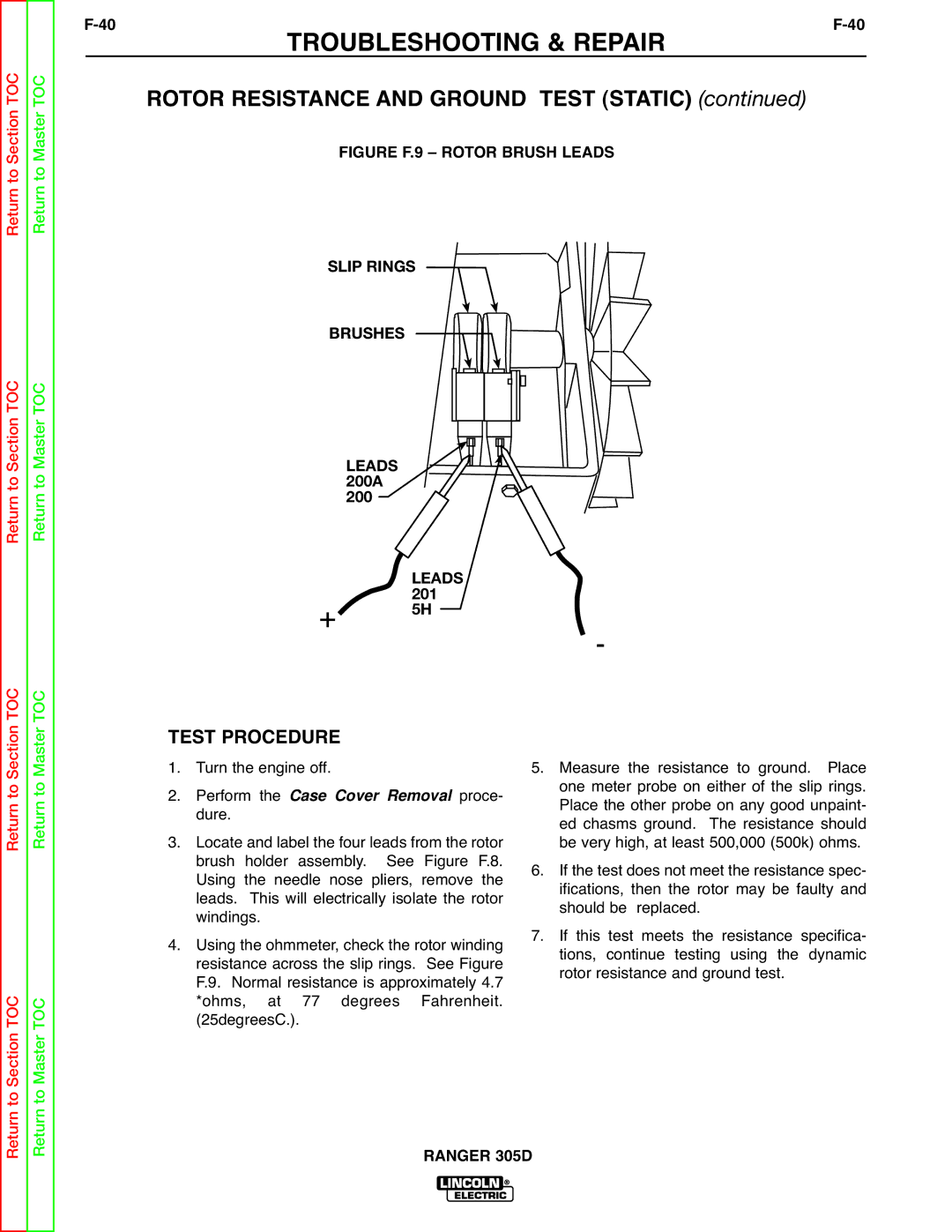
FIGURE F.9 – ROTOR BRUSH LEADS
SLIP RINGS
BRUSHES
LEADS 200A 200
+ | LEADS | - |
| 201 | |
| 5H |
|
Return to Section TOC
to Section TOC
Return to Master TOC
to Master TOC
TEST PROCEDURE | ||
1. | Turn the engine off. | |
2. | Perform the Case Cover Removal proce- | |
3. | dure. |
|
Locate and label the four leads from the rotor | ||
| brush holder assembly. See Figure F.8. | |
| Using the needle nose pliers, remove the | |
| leads. This will electrically isolate the rotor | |
4. | windings. |
|
Using the ohmmeter, check the rotor winding | ||
| resistance across the slip rings. See Figure | |
| F.9. Normal resistance is approximately 4.7 | |
| *ohms, at | 77 degrees Fahrenheit. |
| (25degreesC.). |
|
5.Measure the resistance to ground. Place one meter probe on either of the slip rings. Place the other probe on any good unpaint- ed chasms ground. The resistance should be very high, at least 500,000 (500k) ohms.
6.If the test does not meet the resistance spec- ifications, then the rotor may be faulty and should be replaced.
7.If this test meets the resistance specifica- tions, continue testing using the dynamic rotor resistance and ground test.
Return
Return