Return to Section TOC
Return to Section TOC
Return to Master TOC
Return to Master TOC
TROUBLESHOOTING & REPAIR | ||||||||
| STATOR VOLTAGE TESTS (continued) |
| ||||||
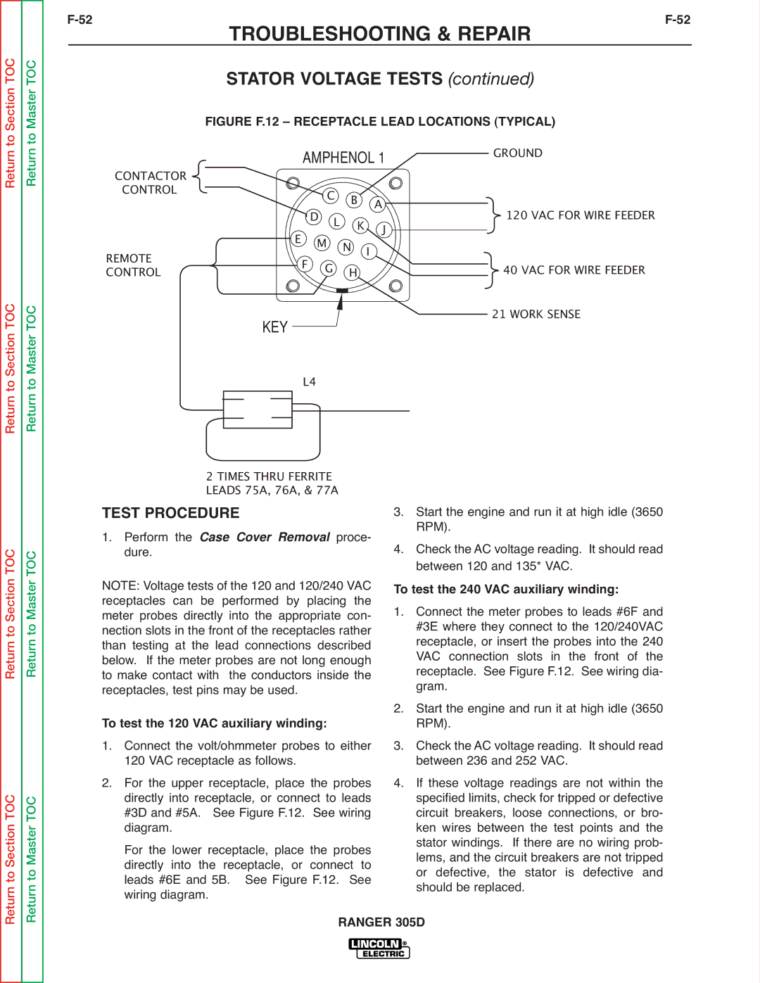
| FIGURE F.12 – RECEPTACLE LEAD LOCATIONS (TYPICAL) |
| ||||||
CONTACTOR |
| AMPHENOL 1 | GROUND |
| ||||
CONTROL |
|
| C B | A |
| 120 VAC FOR WIRE FEEDER |
| |
REMOTE | E | F | DM | L N K I |
| J | 40 VAC FOR WIRE FEEDER |
|
CONTROL |
| G | H |
|
|
| ||
| KEY |
|
|
|
|
| 21 WORK SENSE |
|
|
| L4 |
|
|
|
|
| |
Return to Section TOC
Return to Section TOC
Return to Master TOC
Return to Master TOC
2 TIMES THRU FERRITE
LEADS 75A, 76A, & 77A
TEST PROCEDURE
1. Perform theproce-
dure. Case Cover Removal NOTE: Voltage tests of the 120 and 120/240 VAC receptacles can be performed by placing the meter probes directly into the appropriate con- nection slots in the front of the receptacles rather than testing at the lead connections described below. If the meter probes are not long enough to make contact with the conductors inside the receptacles, test pins may be used.
To test the 120 VAC auxiliary winding:
1. Connect the volt/ohmmeter probes to either
120 VAC receptacle as follows.
2. For the upper receptacle, place the probes directly into receptacle, or connect to leads #3D and #5A. See Figure F.12. See wiring diagram.
For the lower receptacle, place the probes directly into the receptacle, or connect to leads #6E and 5B. See Figure F.12. See wiring diagram.
3. Start the engine and run it at high idle (3650 RPM).
4. Check the AC voltage reading. It should read between 120 and 135* VAC.
To test the 240 VAC auxiliary winding:
1. Connect the meter probes to leads #6F and #3E where they connect to the 120/240VAC receptacle, or insert the probes into the 240 VAC connection slots in the front of the receptacle. See Figure F.12. See wiring dia- gram.
2. Start the engine and run it at high idle (3650 RPM).
3. Check the AC voltage reading. It should read between 236 and 252 VAC.
4. If these voltage readings are not within the specified limits, check for tripped or defective circuit breakers, loose connections, or bro- ken wires between the test points and the stator windings. If there are no wiring prob- lems, and the circuit breakers are not tripped or defective, the stator is defective and should be replaced.
