Return to Section TOC
Return to Section TOC
Return to Section TOC
Return to Section TOC
Return to Master TOC
Return to Master TOC
Return to Master TOC
Return to Master TOC
INSTALLATION | ||||
| REMOTE CONTROL |
| MACHINE GROUNDING |
|
| The RANGER 305D is equipped with both a | Because this portable engine driven welder creates its | ||
| a | own power, it is not necessary to connect its frame to | ||
| primarily used to connect a remote control device, such | an earth ground, unless the machine is connected to | ||
| as a K857, or a TIG Amptrol, such as the K870 or | premises wiring (home, shop, etc.) |
| |
| K812. The | To prevent dangerous electric shock, other equipment | ||
| used to directly connect a wire feeder, TIG module, or | |||
| Spool Gun module control cable. See | Accessories | to which this engine driven welder supplies power | |
| section for more information. |
| must: |
|
| NOTE: Both the | • Be grounded to the frame of the welder using a | ||
| same output control | |||
| ry; for this reason, there can only be one device | grounded type plug or be double insulated. |
| |
| plugged into the Ranger 305D at any time. | WARNING |
| |
| Switch operation is covered in “Operation” section. | Do not ground this machine to a pipe that carries explo- | ||
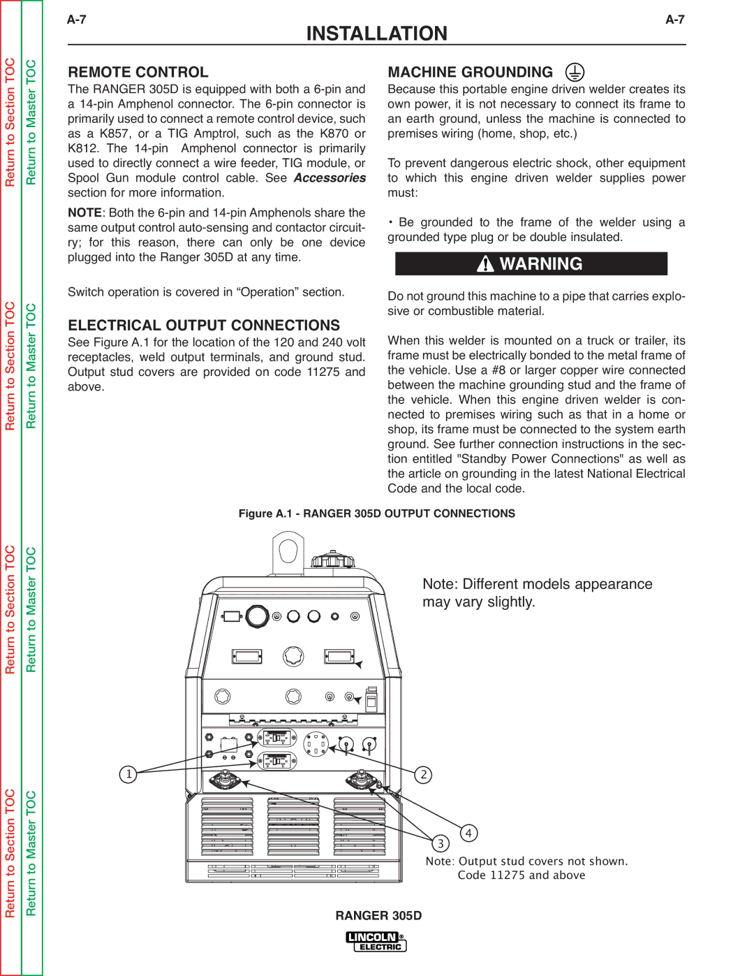
| ELECTRICAL OUTPUT CONNECTIONS | sive or combustible material. |
| |
| See Figure A.1 for the location of the 120 and 240 volt | When this welder is mounted on a truck or trailer, its | ||
| receptacles, weld output terminals, and ground stud. | frame must be electrically bonded to the metal frame of | ||
| Output stud covers are provided on code 11275 and | the vehicle. Use a #8 or larger copper wire connected | ||
| above. |
| between the machine grounding stud and the frame of | |
|
| the vehicle. When this engine driven welder is con- | ||
|
|
| nected to premises wiring such as that in a home or | |
|
|
| shop, its frame must be connected to the system earth | |
|
|
| ground. See further connection instructions in the sec- | |
|
|
| tion entitled "Standby Power Connections" as well as | |
|
|
| the article on grounding in the latest National Electrical | |
|
|
| Code and the local code. |
|
| Figure A.1 - RANGER 305D OUTPUT CONNECTIONS |
| ||
Note: Different models appearance may vary slightly.
1 
![]()
![]() 2
2
3 4
Note: Output stud covers not shown. Code 11275 and above
RANGER 305D