Return to Section TOC
Return to Section TOC
Return to Section TOC
Return to Master TOC
Return to Master TOC
Return to Master TOC
ACCESSORIES |
|
|
|
|
|
|
|
|
| ||||||||
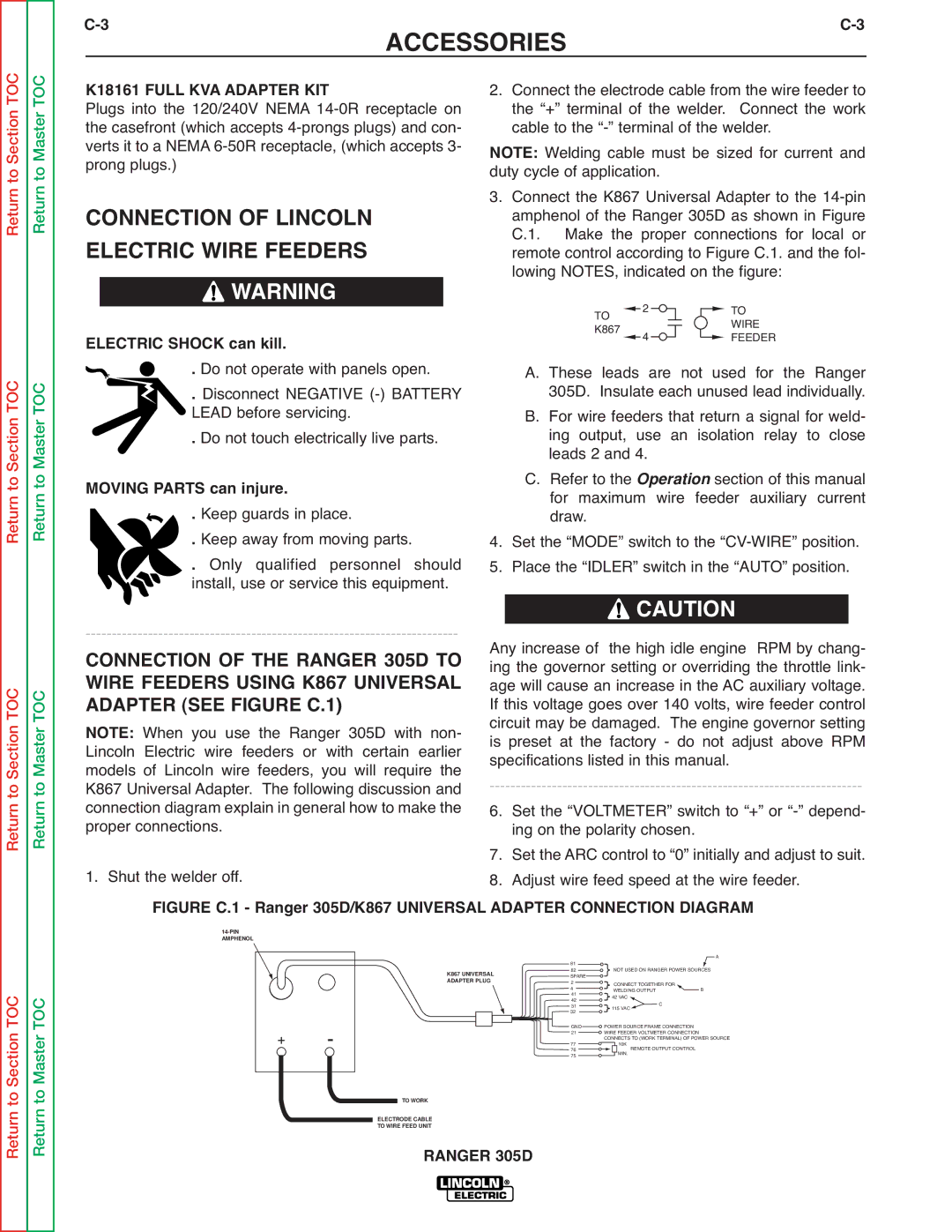
| K18161 FULL KVA ADAPTER KIT | 2. | Connect the electrode cable from the wire feeder to | ||||||||||||||
| Plugs into the 120/240V NEMA |
| the “+” terminal of the welder. | Connect the work | |||||||||||||
| the casefront (which accepts |
| cable to the | ||||||||||||||
| verts it to a NEMA | NOTE: Welding cable must be sized for current and | |||||||||||||||
| prong plugs.) |
|
| duty cycle of application. |
| ||||||||||||
| CONNECTION OF LINCOLN | 3. Connect the K867 Universal Adapter to the | |||||||||||||||
|
| amphenol of the Ranger 305D as shown in Figure | |||||||||||||||
|
| C.1. Make the proper connections for local or | |||||||||||||||
| ELECTRIC WIRE FEEDERS |
| remote control according to Figure C.1. and the fol- | ||||||||||||||
|
|
| WARNING |
|
| lowing NOTES, indicated on the figure: | |||||||||||
|
|
|
|
| TO | 2 |
|
|
|
|
|
|
| TO | |||
|
|
|
|
|
|
|
|
|
|
|
|
|
|
| WIRE | ||
|
|
|
|
|
|
|
|
|
|
|
|
|
|
| |||
|
|
|
|
|
|
|
|
|
|
|
|
|
|
| |||
|
|
|
|
|
|
|
|
|
|
|
|
|
|
| |||
| ELECTRIC SHOCK can kill. |
| K867 |
| 4 |
|
|
|
|
|
|
| FEEDER | ||||
|
|
|
|
|
|
|
|
|
| ||||||||
. | Do not operate with panels open. |
| A. These leads are not used for the Ranger | ||||||||||||||
. | Disconnect NEGATIVE |
| 305D. Insulate each unused lead individually. | ||||||||||||||
|
| LEAD before servicing. |
| B. For wire feeders that return a signal for weld- | |||||||||||||
|
| . Do not touch electrically live parts. |
| ing output, use an isolation relay to close | |||||||||||||
|
|
| leads 2 and 4. |
| |||||||||||||
| MOVING PARTS can injure. |
| C. Refer to the | Operation section of this manual | |||||||||||||
|
| for maximum wire feeder auxiliary current | |||||||||||||||
. | Keep guards in place. | 4. | draw. |
|
|
|
|
|
|
|
|
|
| ||||
. | Keep away from moving parts. | Set the “MODE” switch to the | |||||||||||||||
. | Only qualified personnel should | 5. | Place the “IDLER” switch in the “AUTO” position. | ||||||||||||||
|
| install, use or service this equipment. |
|
| CAUTION | ||||||||||||
|
| ||||||||||||||||
Any increase of the high idle engine RPM by chang- | |||||||||||||||||
| CONNECTION OF THE RANGER 305D TO | ||||||||||||||||
| ing the governor setting or overriding the throttle link- | ||||||||||||||||
| WIRE FEEDERS USING K867 UNIVERSAL | age will cause an increase in the AC auxiliary voltage. | |||||||||||||||
| ADAPTER (SEE FIGURE C.1) | If this voltage goes over 140 volts, wire feeder control | |||||||||||||||
| NOTE: When you use the Ranger 305D with non- | circuit may be damaged. The engine governor setting | |||||||||||||||
| Lincoln Electric wire feeders or with certain earlier | is preset at the factory - do not adjust above RPM | |||||||||||||||
| models of Lincoln wire feeders, you will require the | specifications listed in this manual. |
| ||||||||||||||
| K867 Universal Adapter. The following discussion and | ||||||||||||||||
| connection diagram explain in general how to make the | 6. | Set the “VOLTMETER” switch to “+” or | ||||||||||||||
| proper connections. |
| ing on the polarity chosen. |
| |||||||||||||
| 1. Shut the welder off. | 7. Set the ARC control to “0” initially and adjust to suit. | |||||||||||||||
| 8. | Adjust wire feed speed at the wire feeder. | |||||||||||||||
FIGURE C.1 - Ranger 305D/K867 UNIVERSAL ADAPTER CONNECTION DIAGRAM
Return to Section TOC
Return to Master TOC
+ -
| 81 |
|
| A |
K867 UNIVERSAL | 82 | NOT USED ON RANGER POWER SOURCES | ||
| SPARE | CONNECT TOGETHER FOR |
| |
ADAPTER PLUG | 2 |
| ||
4 | WELDING OUTPUT | B | ||
| 41 | |||
| 42 | 42 VAC | C |
|
| 31 | 115 VAC |
| |
| 32 |
|
| |
| GND | POWER SOURCE FRAME CONNECTION |
| |
| 21 | WIRE FEEDER VOLTMETER CONNECTION |
| |
| 77 | CONNECTS TO (WORK TERMINAL) OF POWER SOURCE | ||
| 10K | REMOTE OUTPUT CONTROL |
| |
| 76 | MIN. |
| |
| 75 |
|
| |
TO WORK
ELECTRODE CABLE
TO WIRE FEED UNITRANGER 305D