4 Operating the Power Supply Remotely

Connecting to the Interfaces

The Agilent N5700 power supplies support remote interface communication using a choice of three interfaces: GPIB, USB, and LAN. All three interfaces are live at power-on.

GPIB Interface


For detailed information about GPIB interface connections, refer to the Agilent

NOTE


Technologies USB/LAN/GPIB Interfaces Connectivity Guide, located on the


Automation-Ready CD-ROM that is shipped with your product.


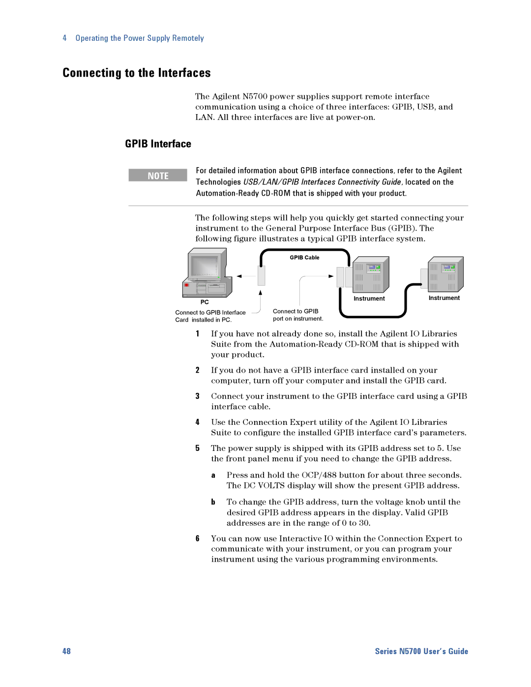
The following steps will help you quickly get started connecting your


instrument to the General Purpose Interface Bus (GPIB). The


following figure illustrates a typical GPIB interface system.


GPIB Cable


PC

Instrument

Instrument


Connect to GPIB Interface

Connect to GPIB


Card installed in PC.

port on instrument.


1If you have not already done so, install the Agilent IO Libraries Suite from the Automation-Ready CD-ROM that is shipped with your product.

2If you do not have a GPIB interface card installed on your computer, turn off your computer and install the GPIB card.

3Connect your instrument to the GPIB interface card using a GPIB interface cable.

4Use the Connection Expert utility of the Agilent IO Libraries Suite to configure the installed GPIB interface card’s parameters.

5The power supply is shipped with its GPIB address set to 5. Use the front panel menu if you need to change the GPIB address.

a Press and hold the OCP/488 button for about three seconds. The DC VOLTS display will show the present GPIB address.

b To change the GPIB address, turn the voltage knob until the desired GPIB address appears in the display. Valid GPIB addresses are in the range of 0 to 30.

6You can now use Interactive IO within the Connection Expert to communicate with your instrument, or you can program your instrument using the various programming environments.

48

Series N5700 User’s Guide

Page 48
Image 48
Agilent Technologies 5752A, 5744A, 5743A, 5748A, 5741A, 5746A, 5751A, 5742A, 5745A Connecting to the Interfaces, Gpib Interface

5751A, 5744A, 5743A, 5750A, 5749A specifications

Agilent Technologies has been a leader in electronic measurement and analysis, with a suite of powerful instruments that cater to various applications in research, development, and manufacturing. Among these, the Agilent 5746A, 5745A, 5741A, 5748A, and 5742A models stand out for their advanced capabilities and features.

The Agilent 5746A is a high-performance signal analyzer that excels in time and frequency domain analysis. This device offers a wide frequency range and exceptional dynamic range, making it suitable for both RF and microwave applications. Its advanced digital signal processing allows for high-resolution spectrum analysis and real-time signal processing, which is essential for engineers and researchers working on complex signals.

The Agilent 5745A is known for its versatility as a multifunctional signal generator. It combines the functionalities of a vector signal generator with the precision of a traditional oscillator. This model provides high-quality waveform generation for a variety of modulation schemes, making it ideal for testing communication systems and conducting research in advanced modulation techniques.

The Agilent 5741A is a precision power meter that offers accurate measurements of RF power in a compact format. It is equipped with state-of-the-art sensing technology that ensures reliable and repeatable measurements. The 5741A is particularly useful for monitoring power levels in transmitters and receivers, and its intuitive interface makes it user-friendly for both novices and experienced professionals.

For those focused on harmonic and intermodulation distortion analysis, the Agilent 5748A provides exceptional performance. This model allows users to analyze distortion products in various devices with precision, helping in the design and testing of amplifiers and other RF components. Its comprehensive sweep functionality enables users to observe the behavior of devices across a wide frequency range.

Finally, the Agilent 5742A complements the range with its dedicated spectrum analyzing capabilities. Offering high sensitivity and ability to capture short-lived events, this model is optimal for monitoring transient signals. The 5742A is frequently used in the telecommunications sector to ensure signal integrity and compliance with regulatory standards.

Together, these Agilent Technologies instruments provide a comprehensive toolkit for professionals in electronics and telecommunications, enabling detailed analysis, accurate measurements, and advanced signal generation. Their integration of modern technologies ensures that users can tackle the complexities of today’s electronic environments with confidence and precision.