Return to Section TOC
Return to Master TOC
TROUBLESHOOTING & REPAIR | |||||||
| STATOR SHORT CIRCUIT & GROUND TEST (continued) |
| |||||
|
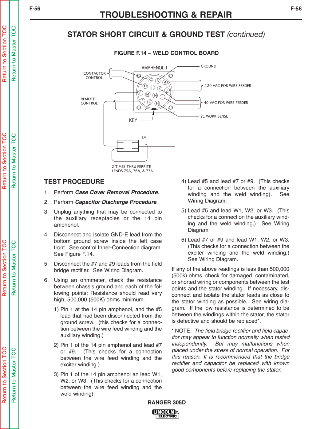
| FIGURE F.14 – WELD CONTROL BOARD |
| ||||
| CONTACTOR |
| AMPHENOL 1 | GROUND |
| ||
| CONTROL |
|
| C B |
|
| |
| REMOTE | E | F | DM | L N K I AJ | 120 VAC FOR WIRE FEEDER |
|
| CONTROL |
| G | H | 40 VAC FOR WIRE FEEDER |
| |
|
|
|
|
|
| 21 WORK SENSE |
|
KEY
Return to Section TOC
Return to Section TOC
Return to Section TOC
Return to Master TOC
Return to Master TOC
Return to Master TOC
TEST PROCEDURE
1. Perform Case Cover Removal Procedure.
2. Performdure.
3. Unplug anythingCapacitorthatDischargemay be Procconnected to the auxiliary receptacles or the 14 pin amphenol.
4. Disconnect and isolate
5. Disconnect the #7 and #9 leads from the field bridge rectifier. See Wiring Diagram.
6. Using an ohmmeter, check the resistance between chassis ground and each of the fol- lowing points; Resistance should read very high, 500,000 (500K) ohms minimum.
1) Pin 1 at the 14 pin amphenol, and the #5 lead that had been disconnected from the ground screw. (this checks for a connec- tion between the wire feed winding and the auxiliary winding.)
2) Pin 1 of the 14 pin amphenol and lead #7 or #9. (This checks for a connection between the wire feed winding and the exciter winding.)
3) Pin 1 of the 14 pin amphenol an lead W1, W2, or W3. (This checks for a connection between the wire feed winding and the weld winding).
4) Lead #5 and lead #7 or #9. (This checks for a connection between the auxiliary winding and the weld winding). See Wiring Diagram.
5) Lead #5 and lead W1, W2, or W3. (This checks for a connection the auxiliary wind- ing and the weld winding.) See Wiring Diagram.
6) Lead #7 or #9 and lead W1, W2, or W3. (This checks for a connection between the exciter winding and the weld winding.) See Wiring Diagram.
If any of the above readings is less than 500,000 (500k) ohms, check for damaged, contaminated, or shorted wiring or components between the test points and the stator winding. If necessary, dis- connect and isolate the stator leads as close to the stator winding as possible. See wiring dia- gram. If the low resistance is determined to be between the windings within the stator, the stator is defective and should be replaced*.
* NOTE: The field bridge rectifier and field capac- itor may appear to function normally when tested independently. But may malfunctions when placed under the stress of normal operation. For this reason, It is recommended that the bridge rectifier and capacitor be replaced with known good components before replacing the stator.