Return to Section TOC
Return to Section TOC
Return to Section TOC
Return to Section TOC
Return to Master TOC
Return to Master TOC
Return to Master TOC
Return to Master TOC
F-92 TROUBLESHOOTING & REPAIRF-92
STATOR/ROTOR REMOVAL AND REPLACEMENT (continued)
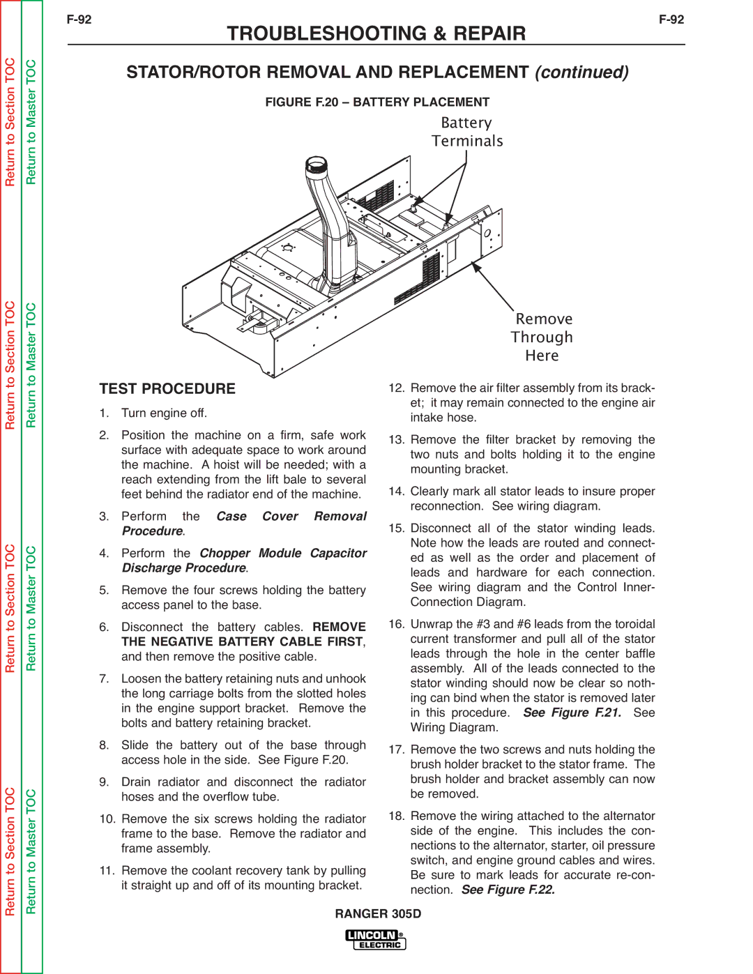
FIGURE F.20 – BATTERY PLACEMENT
TerminalsBattery
|
|
|
| Remove |
| |
|
|
|
| Through |
| |
TEST PROCEDURE |
| Here |
| |||
12. Remove the air filter assembly from its brack- | ||||||
1. | Turn engine off. | et; it may remain connected to the engine air | ||||
intake hose. |
|
| ||||
2. | Position the machine on a firm, safe work | 13. Remove the filter bracket by removing the | ||||
| surface with adequate space to work around | |||||
| the machine. A hoist will be needed; with a | two nuts and bolts holding it to the engine | ||||
| reach extending from the lift bale to several | mounting bracket. |
|
| ||
3. | feet behind the radiator end of the machine. | 14. Clearly mark all stator leads to insure proper | ||||
Perform the | Case Cover Removal | reconnection. See wiring diagram. | leads. | |||
| rocedure |
| 15. Disconnect all of | the stator winding | ||
| . |
| Note how the leads are routed and connect- | |||
4. | Perform the Chopper Module Capacitor | |||||
ed as well as the order and placement of | ||||||
5. | Discharge Pr | cedure. | leads and hardware for each connection. | |||
Remove the four screws holding the battery | See wiring diagram and the Control Inner- | |||||
6. | access panel to the base. | Connection Diagram. |
| |||
Disconnect the battery cables. REMOVE | 16. Unwrap the #3 and #6 leads from the toroidal | |||||
| THE NEGATIVE BATTERY CABLE FIRST, | current transformer and pull all of the stator | ||||
| and then remove the positive cable. | leads through the hole in the center baffle | ||||
7. | Loosen the battery retaining nuts and unhook | assembly. All of the leads connected to the | ||||
stator winding should now be clear so noth- | ||||||
| the long carriage bolts from the slotted holes | ing can bind when the stator is removed later | ||||
| in the engine support bracket. Remove the | in this procedure. | See Figure F.21. | See | ||
8. | bolts and battery retaining bracket. | Wiring Diagram. |
|
| ||
Slide the battery out of the base through | 17. Remove the two screws and nuts holding the | |||||
9. | access hole in the side. See Figure F.20. | brush holder bracket to the stator frame. The | ||||
Drain radiator and disconnect the radiator | brush holder and bracket assembly can now | |||||
10. | hoses and the overflow tube. | be removed. |
|
| ||
Remove the six screws holding the radiator | 18. Remove the wiring attached to the alternator | |||||
| frame to the base. Remove the radiator and | side of the engine. This includes the con- | ||||
| frame assembly. | nections to the alternator, starter, oil pressure | ||||
11. | Remove the coolant recovery tank by pulling | switch, and engine ground cables and wires. | ||||
Be sure to mark leads for accurate | ||||||
| it straight up and off of its mounting bracket. | nection. See Figure F.22. |
| |||
|
| RANGER 305D |
|
| ||