Return to Section TOC
Return to Section TOC
Return to Section TOC
Return to Section TOC
Return to Master TOC
Return to Master TOC
Return to Master TOC
Return to Master TOC
|
|
|
|
|
|
|
| ||
TROUBLESHOOTING & REPAIR |
|
|
|
|
| ||||
TROUBLESHOOTING GUIDE |
|
|
| Observe Safety Guidelines | |||||
| detailed in the beginning of this manual. | ||||||||
|
|
|
|
|
| ||||
PROBLEMS | POSSIBLE AREAS OF |
| RECOMMENDED |
|
| ||||
(SYMPTOMS) | MISADJUSTMENT(S) |
| COURSE OF ACTION | ||||||
|
|
|
|
|
|
|
|
| |
| WELD OUTPUT PROBLEMS |
|
|
|
|
|
|
| |
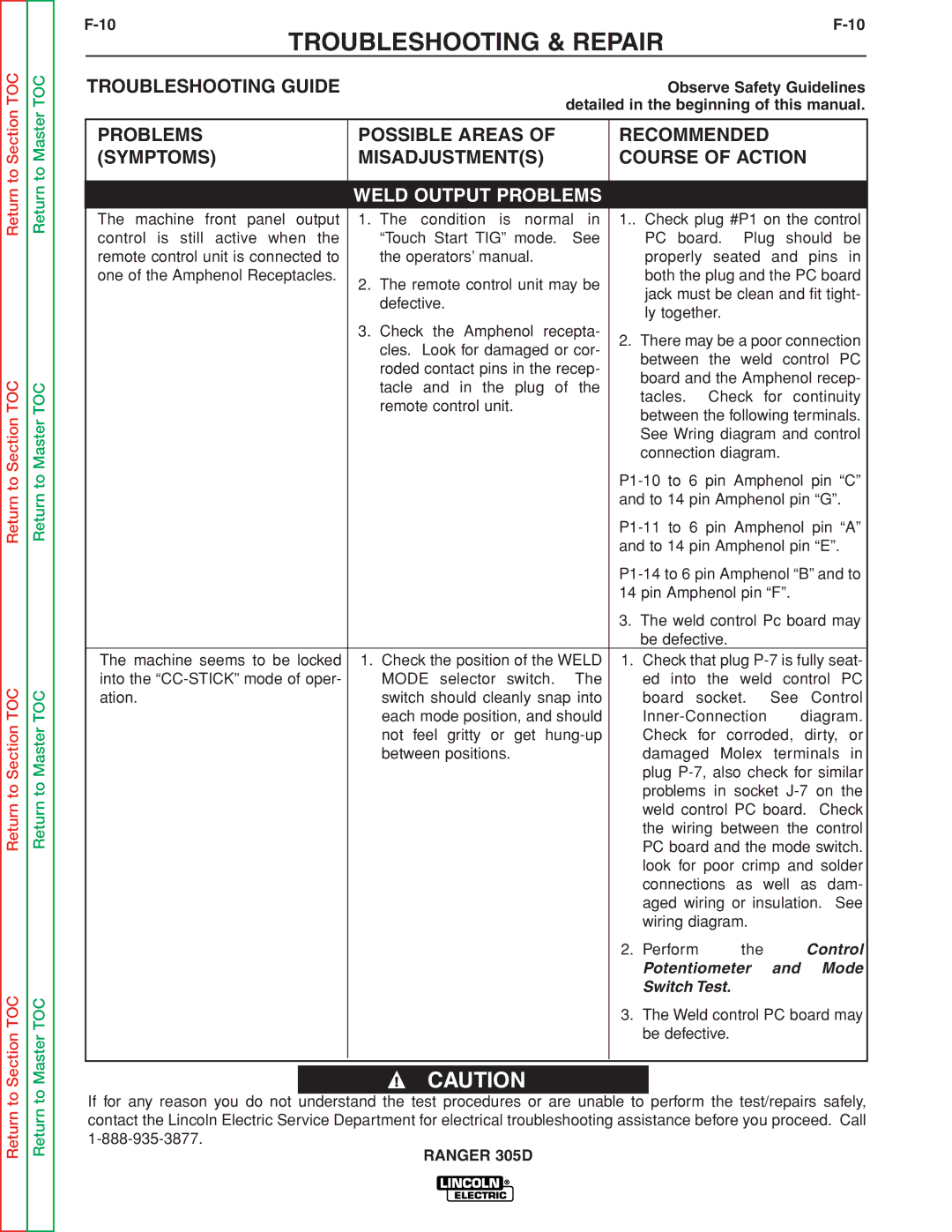
The machine front panel output | 1. The condition is normal in | 1.. Check plug #P1 on the control | |||||||
control is still active when the | “Touch Start TIG” mode. | See |
| PC board. | Plug | should be | |||
remote control unit is connected to | the operators’ manual. |
|
| properly seated and pins in | |||||
one of the Amphenol Receptacles. | 2. The remote control unit may be |
| both the plug and the PC board | ||||||
|
| jack must be clean and fit tight- | |||||||
| defective. |
|
| ||||||
|
|
| ly together. |
|
|
|
| ||
|
|
|
|
|
|
|
| ||
| 3. Check the Amphenol recepta- | 2. There may be a poor connection | |||||||
| cles. Look for damaged or cor- | ||||||||
|
| between | the | weld | control PC | ||||
| roded contact pins in the recep- |
| |||||||
|
| board and the Amphenol recep- | |||||||
| tacle and in the plug of | the |
| ||||||
|
| tacles. | Check | for | continuity | ||||
| remote control unit. |
|
| ||||||
|
|
| between the following terminals. | ||||||
|
|
|
| ||||||
|
|
|
| See Wring diagram and control | |||||
|
|
|
| connection diagram. |
|
| |||
|
|
| |||||||
|
|
| and to 14 pin Amphenol pin “G”. | ||||||
|
|
| |||||||
|
|
| and to 14 pin Amphenol pin “E”. | ||||||
|
|
| |||||||
|
|
| 14 pin Amphenol pin “F”. |
| |||||
|
|
| 3. The weld control Pc board may | ||||||
|
|
|
| be defective. |
|
|
|
| |
The machine seems to be locked | 1. Check the position of the WELD | 1. | Check that plug | ||||||
into the | MODE selector switch. | The |
| ed into the weld control PC | |||||
ation. | switch should cleanly snap into |
| board socket. | See | Control | ||||
| each mode position, and should |
|
| diagram. | |||||
| not feel gritty or get |
| Check for corroded, dirty, or | ||||||
| between positions. |
|
| damaged Molex | terminals in | ||||
|
|
|
| plug | |||||
|
|
|
| problems in socket | |||||
|
|
|
| weld control PC board. Check | |||||
|
|
|
| the wiring between the control | |||||
|
|
|
| PC board and the mode switch. | |||||
|
|
|
| look for poor crimp and solder | |||||
|
|
|
| connections as well as dam- | |||||
|
|
|
| aged wiring or insulation. See | |||||
|
|
|
| wiring diagram. |
|
|
| ||
|
|
| 2. | Perform |
| the |
|
| Control |
|
|
|
| Potentiometer | and | Mode | |||
|
|
|
| Switch Test. |
|
|
|
| |
|
|
| 3. The Weld control PC board may | ||||||
|
|
|
| be defective. |
|
|
|
| |
|
|
|
|
|
|
|
|
|
|
|
|
|
|
|
|
|
|
|
|
CAUTION
If for any reason you do not understand the test procedures or are unable to perform the test/repairs safely, contact the Lincoln Electric Service Department for electrical troubleshooting assistance before you proceed. Call
