Return to Master TOC
Return to Master TOC
Return to Master TOC
Return to Master TOC
Section | TABLE OF CONTENTS | Section | |
TROUBLESHOOTING & REPAIR SECTION |
| ||
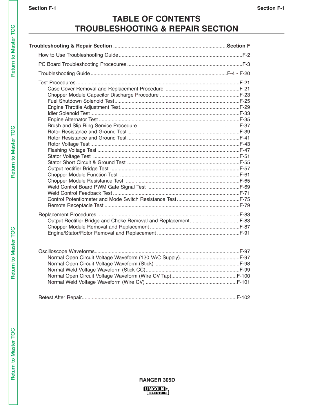
Troubleshooting & Repair Section | ................................................................................ | Section F | |
How to Use Troubleshooting Guide | |||
PC Board Troubleshooting Procedures | |||
Troubleshooting Guide | |||
Test Procedures | |||
Case Cover Removal and Replacement Procedure | |||
Chopper Module Capacitor Discharge Procedure | |||
Fuel Shutdown Solenoid Test | |||
Engine Throttle Adjustment Test | |||
Idler Solenoid Test | |||
Engine Alternator Test | |||
Brush and Slip Ring Service Procedure | |||
Rotor Resistance and Ground Test | |||
Rotor Resistance and Ground Test | |||
Rotor Voltage Test | |||
Flashing Voltage Test | |||
Stator Voltage Test | |||
Stator Short Circuit & Ground Test | |||
Output rectifier Bridge Test | |||
Chopper Module Function Test | |||
Chopper Module Resistance Test | |||
Weld Control Board PWM Gate Signal Test | |||
Weld Control Feedback Test | ......................................................................................... | ||
Control Potentiometer and Mode Switch Resistance Test | |||
Remote Receptacle Test | |||
Replacement Procedures | |||
Output Rectifier Bridge and Choke Removal and Replacement | |||
Chopper Module Removal and Replacement | |||
Engine/Stator/Rotor Removal and Replacement | |||
Oscilloscope Waveforms | |||
Normal Open Circuit Voltage Waveform (120 VAC Supply) | |||
Normal Open Circuit Voltage Waveform (Stick) | |||
Normal Weld Voltage Waveform (Stick CC) | |||
Normal Open Circuit Voltage Waveform (Wire CV Tap) | |||
Normal Weld Voltage Waveform (Wire CV) | |||
Retest After Repair | |||
