Return to Section TOC
Return to Section TOC
Section TOC
Return to Master TOC
Return to Master TOC
Master TOC
ACCESSORIES | ||||||
| CONNECTION OF THE | 5. | Place the “IDLER” switch in the “HIGH” position. | |||
| RANGER 305D USING K595 CONTROL |
| CAUTION |
| ||
| CABLE |
|
|
| ||
| (SEE FIGURE C.6.) |
| Any increase of the high idle engine RPM by changing | |||
| NOTE: If your | the governor setting or overriding the throttle linkage | ||||
| K404 input cable, refer to CONNECTIONS OF THE | will cause an increase in the AC auxiliary voltage. If | ||||
| this voltage goes over 140 volts, wire feeder control cir- | |||||
| this discussion, to connect your Ranger 305D for wire | cuit may be damaged. The engine governor setting is | ||||
| feed welding. |
| preset at the factory - do not adjust above RPM speci- | |||
1. | Shut the welder off. |
| fications listed in this manual. |
| ||
| ||||||
2. | Connect the electrode cable from the | 6. | Set the “VOLTMETER” switch to “+” or | |||
|
| “+” terminal of the welder. Connect the work cable |
| ing on the polarity chosen. |
| |
|
| to the |
| 7. | Set the “MODE” switch to |
|
| NOTE: Welding cable must be sized for current and |
| ||||
| duty cycle of application. |
| 8. | Set the “WELD TERMINALS” switch to “WELD |
| |
| NOTE: Figure C.5 shows the electrode connected for |
| TERMINALS REMOTELY CONTROLLED.” |
| ||
| positive polarity. To change polarity, shut the welder | 9. | Adjust wire feed speed and voltage at the | |||
| off and reverse the electrode and work cables at the | |||||
| output terminals. |
| 10. Adjust the “ARC” control to “0” initially and adjust | |||
3. | Connect the |
| to suit. |
| ||
| 4. Connect the |
|
|
| ||
|
| the Ranger 305D. |
|
|
|
|
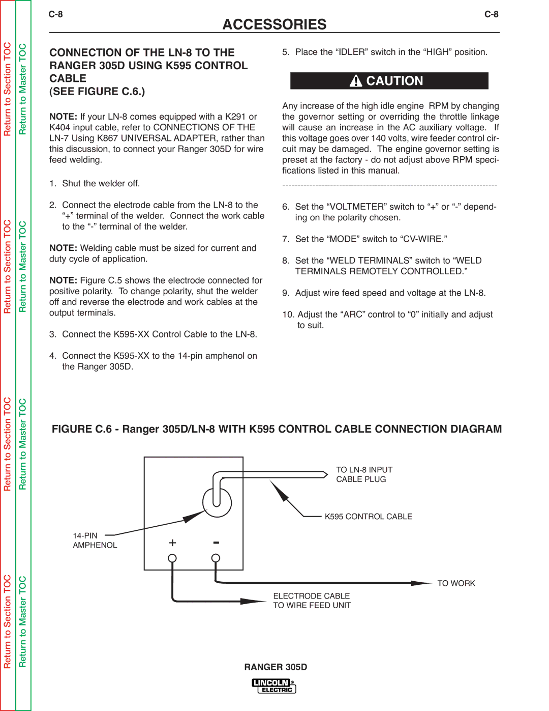
FIGURE C.6 - Ranger 305D/LN-8 WITH K595 CONTROL CABLE CONNECTION DIAGRAM
TO
CABLE PLUG
+ | - | K595 CONTROL CABLE |
|
|
|
| |
|
| ELECTRODE CABLE | TO WORK |
|
| TO WIRE FEED UNIT |
|