Return to Section TOC
Return to Section TOC
Return to Master TOC
Return to Master TOC
F-53 TROUBLESHOOTING & REPAIRF-53
STATOR VOLTAGE TESTS (continued)
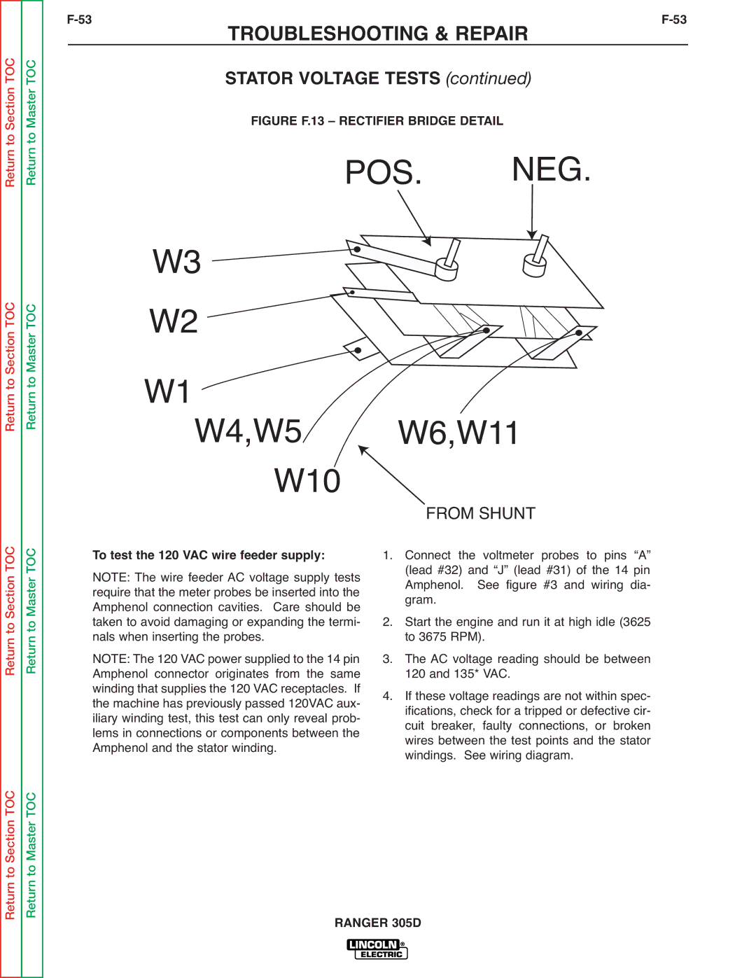
FIGURE F.13 – RECTIFIER BRIDGE DETAIL
POS. NEG.
W3
W2 ![]()
![]()
![]()
![]()
W1W4,W5 W6,W11
W10  FROM SHUNT
Return to Section TOC
Return to Master TOC
To test the 120 VAC wire feeder supply: NOTE: The wire feeder AC voltage supply tests require that the meter probes be inserted into the Amphenol connection cavities. Care should be taken to avoid damaging or expanding the termi- nals when inserting the probes.
NOTE: The 120 VAC power supplied to the 14 pin Amphenol connector originates from the same winding that supplies the 120 VAC receptacles. If the machine has previously passed 120VAC aux- iliary winding test, this test can only reveal prob- lems in connections or components between the Amphenol and the stator winding.
1.Connect the voltmeter probes to pins “A” (lead #32) and “J” (lead #31) of the 14 pin Amphenol. See figure #3 and wiring dia- gram.
2.Start the engine and run it at high idle (3625 to 3675 RPM).
3.The AC voltage reading should be between 120 and 135* VAC.
4.If these voltage readings are not within spec- ifications, check for a tripped or defective cir- cuit breaker, faulty connections, or broken wires between the test points and the stator windings. See wiring diagram.
Return to Section TOC
Return to Master TOC