Section TOC
Master TOC
THEORY OF OPERATION | |||
|
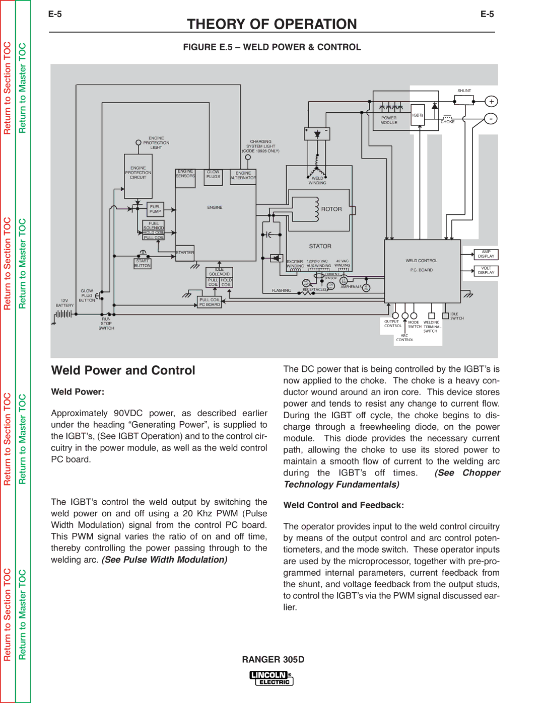
| FIGURE E.5 – WELD POWER & CONTROL |
|
Return to
Return to Section TOC
Return to
Return to Master TOC
12V.
BATTERY
GLOW
PLUG
BUTTON
RUN
STOP
SWITCH
|
|
| SHUNT | + |
|
|
|
| |
POWER | IGBTs | CHOKE |
| - |
MODULE |
|
|
ENGINE |
|
| CHARGING |
|
PROTECTION |
|
|
| |
LIGHT |
|
| SYSTEM LIGHT |
|
|
|
| (CODE 10926 ONLY) |
|
ENGINE | ENGINE | GLOW | ENGINE |
|
PROTECTION | WELD | |||
CIRCUIT | SENSORS | PLUGS | ALTERNATOR | |
|
|
|
| WINDING |
PUMP | ENGINE |
|
| ROTOR |
|
|
|
| |||
FUEL |
|
|
|
|
|
|
|
|
| ||
FUEL |
|
|
|
|
|
|
|
|
|
|
|
SOLENIOD |
|
|
|
|
|
|
|
|
|
|
|
HOLD COIL |
|
|
|
|
|
|
|
|
|
|
|
PULL COIL |
|
|
|
| STATOR |
|
|
|
|
|
|
START | STARTER |
| EXCITER |
| 42 VAC | WELD CONTROL | AMP | ||||
IDLE | 120/240 VAC | DISPLAY | |||||||||
BUTTON | WINDING AUX.WINDING | WINDING |
| P.C. BOARD | VOLT | ||||||
| SOLENOID |
| 240 | CURRENT |
|
|
| DISPLAY | |||
| PULL | HOLD |
| SENSOR | 14 | 6 |
|
|
| ||
| COIL | COIL | FLASHING | VAC | 120 |
| PIN |
|
|
| |
| PULL COIL |
| RECEPTACLES vac |
| AMPHENALS | PIN |
|
|
| ||
|
|
|
|
|
|
|
|
|
|
| |
| PC BOARD |
|
|
|
|
|
|
|
|
| IDLE |
|
|
|
|
|
|
|
| OUTPUT | MODE | WELDING | |
|
|
|
|
|
|
|
| SWITCH | |||
|
|
|
|
|
|
|
| CONTROL | SWITCH TERMINAL |
| |
|
|
|
|
|
|
|
| ARC |
| SWITCH |
|
|
|
|
|
|
|
|
| CONTROL |
|
| |
Return to Section TOC
to Section TOC
Return to Master TOC
to Master TOC
Weld Power and Control
Weld Power:
Approximately 90VDC power, as described earlier under the heading “Generating Power”, is supplied to the IGBTʼs, (See IGBT Operation) and to the control cir- cuitry in the power module, as well as the weld control PC board.
The IGBTʼs control the weld output by switching the weld power on and off using a 20 Khz PWM (Pulse Width Modulation) signal from the control PC board. This PWM signal varies the ratio of on and off time, thereby controlling the power passing through to the welding arc. (See Pulse Width Modulation)
The DC power that is being controlled by the IGBTʼs is now applied to the choke. The choke is a heavy con- ductor wound around an iron core. This device stores power and tends to resist any change to current flow. During the IGBT off cycle, the choke begins to dis- charge through a freewheeling diode, on the power module. This diode provides the necessary current path, allowing the choke to use its stored power to maintain a smooth flow of current to the welding arc during the IGBTʼs off times. (See Chopper
Technology Fundamentals)
Weld Control and Feedback:
The operator provides input to the weld control circuitry by means of the output control and arc control poten- tiometers, and the mode switch. These operator inputs are used by the microprocessor, together with
Return
Return