Return to Section TOC
Return to Master TOC
F-58 TROUBLESHOOTING & REPAIRF-58
OUTPUT RECTIFIER BRIDGE TEST (continued)
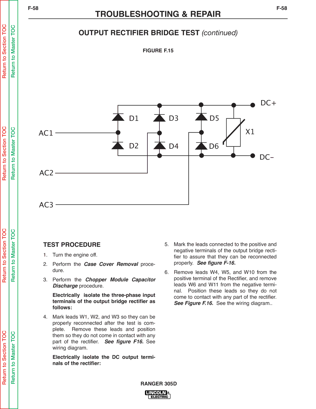
FIGURE F.15
Return to Section TOC
Return to Master TOC
AC1
AC2
AC3
D1 | D3 |
D2 ![]() D4
D4
![]() D5
D5  D6
D6
DC+
X1
DC-
Return to Section TOC
to Section TOC
Return to Master TOC
to Master TOC
TEST PROCEDURE |
| |
1. | Turn the engine off. |
|
2. | Perform the Case Cover Removal proce- | |
3. | dure. |
|
Perform the Chopper Module Capacitor | ||
| Dis harge procedure. |
|
| Electrically isolate the | |
| terminals of the output bridge rectifier as | |
4. | follows: |
|
Mark leads W1, W2, and W3 so they can be | ||
| properly reconnected after the test is com- | |
| plete. Remove these leads and position | |
| them so they do not come in contact with any | |
| part of the rectifier. | See figure F16. See |
| wiring diagram. |
|
Electrically isolate the DC output termi- nals of the rectifier:
5.Mark the leads connected to the positive and negative terminals of the output bridge recti- fier to assure that they can be reconnected properly. See figure
6.Remove leads W4, W5, and W10 from the positive terminal of the Rectifier, and remove leads W6 and W11 from the negative termi- nal. Position these leads so they do not come to contact with any part of the rectifier. See Figure F.16. See the wiring diagram..
Return
Return