FRONT VIEW
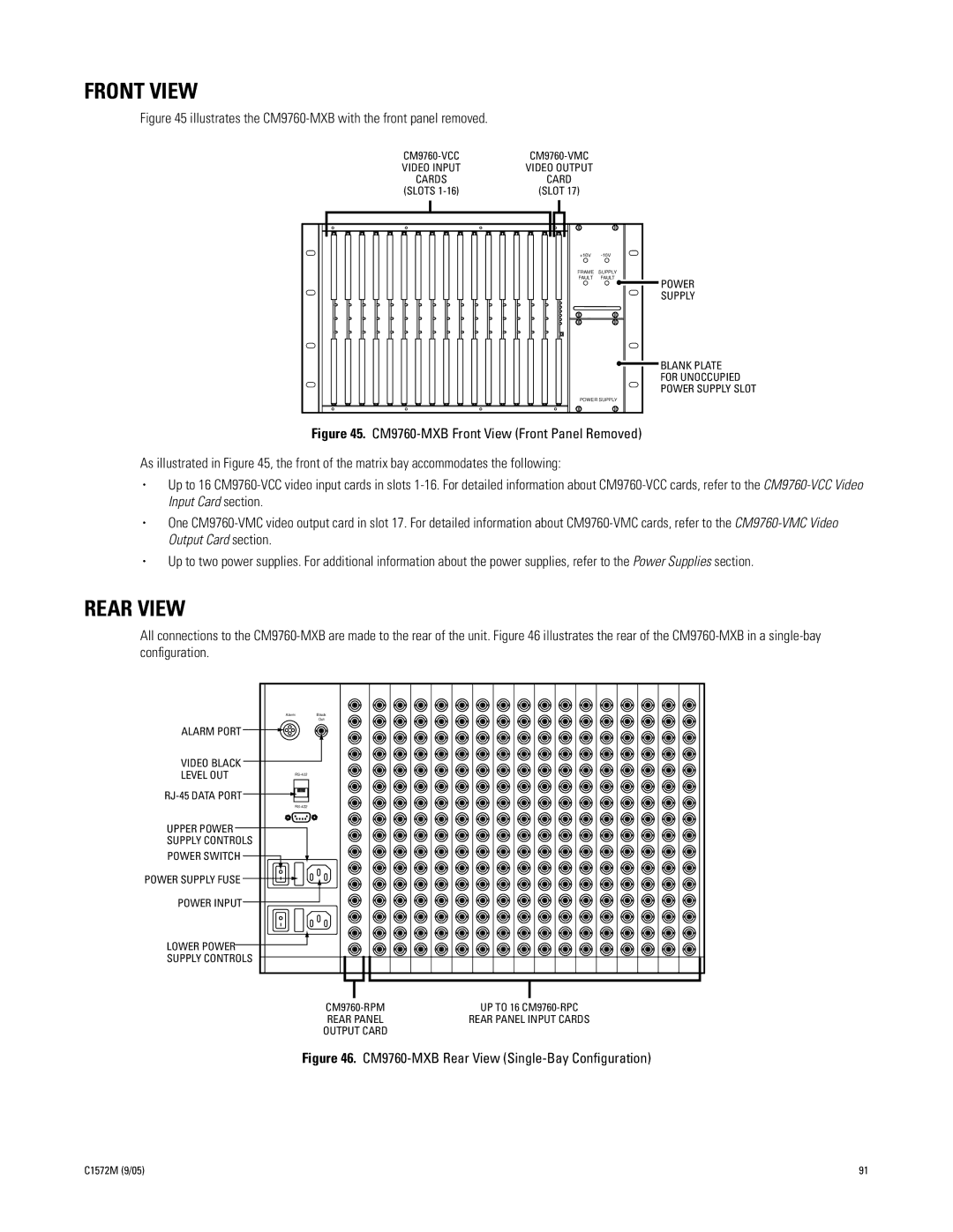
Figure 45 illustrates the CM9760-MXB with the front panel removed.
| ||
VIDEO INPUT | VIDEO OUTPUT |
|
CARDS | CARD |
|
(SLOTS | (SLOT 17) |
|
| +10V | |
| FRAME SUPPLY | |
| FAULT | FAULT |
POWER SUPPLY
POWER
SUPPLY
BLANK PLATE FOR UNOCCUPIED POWER SUPPLY SLOT
Figure 45. CM9760-MXB Front View (Front Panel Removed)
As illustrated in Figure 45, the front of the matrix bay accommodates the following:
•Up to 16 CM9760-VCC video input cards in slots 1-16. For detailed information about CM9760-VCC cards, refer to the CM9760-VCC Video Input Card section.
•One CM9760-VMC video output card in slot 17. For detailed information about CM9760-VMC cards, refer to the CM9760-VMC Video Output Card section.
•Up to two power supplies. For additional information about the power supplies, refer to the Power Supplies section.
REAR VIEW
All connections to the
| Alarm | Black |
|
| Out |
ALARM PORT |
|
|
VIDEO BLACK |
|
|
LEVEL OUT |
| |
|
| |
|
| |
|
| |
UPPER POWER |
|
|
SUPPLY CONTROLS |
|
|
POWER SWITCH |
|
|
POWER SUPPLY FUSE |
|
|
POWER INPUT |
|
|
LOWER POWER |
|
|
SUPPLY CONTROLS |
|
|
UP TO 16 | |
REAR PANEL | REAR PANEL INPUT CARDS |
OUTPUT CARD |
|
Figure 46. CM9760-MXB Rear View (Single-Bay Configuration)
C1572M (9/05) | 91 |