Manuals
/
Pelco
/
Computer Equipment
/
Webcam
Pelco
System 9760
manual
Fuse Locations on CM9760-VCC and CM9760-VMC Cards
Models:
System 9760
1
28
148
148
Download
148 pages
41.95 Kb
25
26
27
28
29
30
31
32
Troubleshooting
Specs
Install
CM9760-MXB Alarm Port
Connecting the CM9700-CC1
Checking Diagnostic Leds
System Setup
DOS Command Reference
Pins 3 to 4 only
Safety
Page 28
Image 28
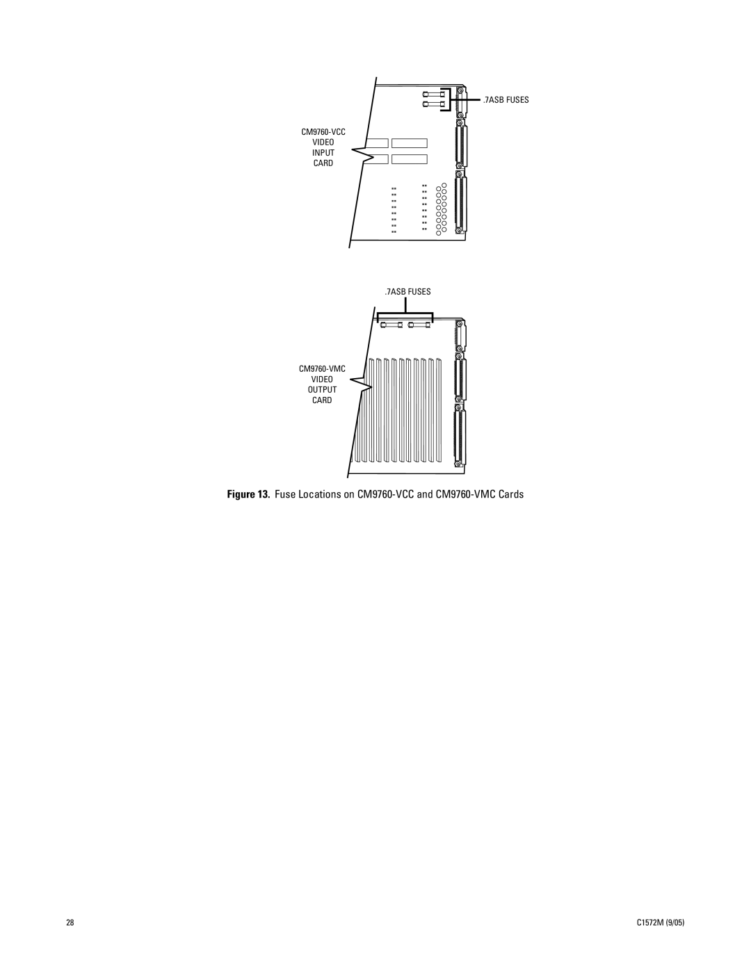
.7ASB FUSES
CM9760-VCC
VIDEO
INPUT
CARD
.7ASB FUSES
CM9760-VMC
VIDEO
OUTPUT
CARD
Figure 13.
Fuse Locations on
CM9760-VCC
and
CM9760-VMC
Cards
28
C1572M (9/05)
Page 27
Page 29
Page 28
Image 28
Page 27
Page 29
Contents
System
Page
Contents
Testport Directory DOS Directory
List of Illustrations
C1572M 9/05
List of Tables
Important Safety Instructions
CM9700-CC1
Regulatory Notices
CM9760-MXB
System Overview
Description
Models
CPU Controller and Components
Matrix BAY and Components
Keyboards
Optional Components
Network Interface Unit
Compatible Receivers
System Setup
System Setup Overview
Unpacking the CM9700-CC1
Unpacking
Unpacking the CM9760-MXB
Selecting a Location for the CM9700-CC1
Installing the CM9700-CC1 Controller
Mounting the CM9700-CC1
Unit
Connecting the CM9700-CC1
Connecting the CM9700-MGR PC to the CM9700-CC1
Connecting a VGA Monitor to the CM9700-CC1
Connecting a PS/2 Keyboard to the CM9700-CC1
System 9760 Factory Default Port Settings
CM9760-HS Port CM9760-MXBs
Connected through the hot switch Other devices
Sequential ports
Connecting Power to the CM9700-CC1
CM9760-HS Port CM9700-NW1
Matrix bays
Interface unit Matrix bays
Powering on the CM9700-CC1
Installing CM9760-MXB Matrix Bays
Selecting a Location for the CM9760-MXB
Mounting the CM9760-MXB
Verifying CM9760-MXB Component Installation
Sample Downframe Cable Connections
Removing the CM9760-MXB Front Panel
CM9760-MXB Front Panel
Connecting the CM9760-MXB to the CM9700-CC1
CM9760-MXB to CM9700-CC1 Connection
Powering on the CM9760-MXB
Connecting Power to the CM9760-MXB
Checking Diagnostic Leds
CM9760-VCC and CM9760-VMC Diagnostic LEDs
Fuse Locations on CM9760-VCC and CM9760-VMC Cards
Connecting Video Inputs and Video Outputs
241
Verifying System Operation
Enter Monitor #
CM9700-CC1 Component Installation or Replacement
Removing the CM9700-CC1 TOP Cover
Installing or Replacing a CM9700-SER Card
ISA Slot Number W1 IRQ Setting W2 Address Setting
IRQ Pins 1 to 2 and 3 to Pins 1 to 2 only
Pins 3 to 4 only
No jumpers
CM9760-MXB Component Installation or Replacement
Installing or Replacing Rear Panel Cards
Installing or Replacing a CM9760-RPC Rear Panel Input Card
Installing a CM9760-RPC Card
Termination Jumpers on CM9760-RPC Rear Panel Input Card
Replacing a CM9760-RPC Card
Installing or Replacing a CM9760-RPL Rear Panel Looping Card
Installing a CM9760-RPL Card
Replacing a CM9760-RPL Card
Installing or Replacing a CM9760-DFC Downframe Card
Installing a CM9760-DFC Card
Replacing a CM9760-DFC Card
Installing or Replacing a CM9760-DFL Downframe Looping Card
Installing a CM9760-DFL Card
Replacing a CM9760-DFL Card
Installing or Replacing a CM9760-RPM Rear Panel Output Card
Installing a CM9760-RPM Card
Replacing a CM9760-RPM Card
Installing a CM9760-VCC Card
Installing or Replacing a CM9760-VCC Video Input Card
Slot Physical
CM9760-VCC Video Input Card Installation Slots
Replacing a CM9760-VCC Card
Installing or Replacing a CM9760-VMC Video Output Card
Installing a CM9760-VMC Card
JP2 X55
Switch
Function
CM9760-VMC Video Output Card Installation Slot
Installing a CM9760-VMM Video Output Module
Replacing a CM9760-VMC Card
Installing or Replacing a Power Supply
Installing a Backup Power Supply
Replacing a Power Supply
Replacing a Power Supply Fuse
CM9760-MXB Power Supply Fuse Replacement
ENABLING/DISABLING the Power Supply Alarm
System Programming Using DOS
Performing System 9760 DOS Programming Tasks
Setting and Adjusting System Time in a SINGLE-NODE System
Setting System Time in a Single-Node System
14 00
Adjusting System Time in a Single-Node System
0230.00
Making Additional Adjustments to System Time
0228.0
CM9700 NODEx /Tmmsshh where
Setting and Adjusting System Time in a MULTI-NODE System
Setting System Time in a Multi-Node System
Adjusting System Time in a Multi-Node System
C1572M 9/05
Making Additional Adjustments to System Time
Editing the Net.bat File to Permanently Adjust System Time
DOS Command Reference
DOS Filename Conventions
File and Disk Management Commands
DEL
Command† Switch†† Description Examples§¶
Specified command About the DIR command
Type command When viewing a long Text file. When More
Redirection operator Symbol is used.
Briefly describes
System Diagnostics
Monitoring CM9700-CC1 Functions
Viewing Monitor BOX Diagnostics
Allocating Monitors to Monitor Boxes
Entering CM9700-CC1 PC Keyboard Commands
System Box Display Message
Updated Demo Off
Alt+T Resynch Trap Offline Resynch Trap Online
Alt+D Demo On
Alt+S System on
Sample CM9700-NW1 Diagnostic Screen
Viewing MULTI-NODE System Status
Entering CM9700-NW1 PC Keyboard Commands
Troubleshooting
General Troubleshooting Guidelines
Troubleshooting the CM9700-CC1
Hardware Error Possible Cause Corrective Action
System Error Message Possible Cause Corrective Action
Troubleshooting the CM9760-MXB
LED Color Possible Cause Corrective Action
CM9700-CC1 Controller
Front View
Illustrates the front of the CM9700-CC1
Rear View
Illustrates the rear of the CM9700-CC1
CM9700-CC1 Rear Connector Pinouts
Directory Structure
DOS DIR
NODEx.GPI GPI setup file
Directory
Testport Directory
DOS Directory
CM9760-MXB Matrix Bay
Functional System Overview
Video Signal Flow through the Matrix Bay
Illustrates the CM9760-MXB with the front panel removed
CM9760-MXB Alarm Port
Not Used
Video Input and Output Cards
CM9760-VCC Video Input Card
CM9760-VCC Card Guidelines
Following guidelines apply to the CM9760-VCC card
CM9760-VMC Video Output Card
CM9760-RPC Rear Panel Input Card
Rear Panel Cards
CM9760-VMC Card Guidelines
CM9760-RPL Rear Panel Looping Card
CM9760-RPC Card Guidelines
CM9760-RPL Card Guidelines
Terminated Unterminated OUT BNC Pairs
CM9760-RPM Card Guidelines
CM9760-RPM Rear Panel Output Card
Following guidelines apply to the CM9760-RPM card
CM9760-DFC Card Guidelines
CM9760-DFC Rear Panel Downframe Card
Following guidelines apply to the CM9760-DFC card
CM9760-DFL Rear Panel Downframe Looping Card
Power Supplies
CM9760-DFL Card Guidelines
Sideframing and Downframing
Sideframing
481 257 241
104 C1572M 9/05
Downframing
241
106 C1572M 9/05
Using a Combination of Sideframing and Downframing
481 257 241
Downframing to the CM9760-MXBL
241
Cams
256
CM9760-MXB Specifications
CM9700-CC1 Specifications
Specifications
Appendix A. CM9700-CC1 Ascii Protocol Communication
Connecting AN ACD DB9 Port to a CM9700-CC1 DB9 Port
ACD to CM9700-CC1 Connections
Connecting AN ACD DB9 Port to a CM9700-CC1 RJ-45 Port
PV140
Ascii Protocol Commands Supported by the CM9700-CC1
Table O. Ascii Command Summary
Action Command
Select Monitor 9999Ma Lock Camera to Monitor
~Ga
Select Camera 999999#a
Lock Next Camera Previous Camera
Action Command Command Description Pan and Tilt Commands
Action Command Command Description
Action Command Command Description Advanced Commands
Matrix Control Commands
Digital Zoom ym command
Select Multiplexer Input command for each input
Digital Zoom
Then again in a 4X magnification
Table Q. Ascii Command Examples
47Ra33Da
C1572M 9/05 121
SIDEFRAME-ONLY Configuration Examples
Illustrate sideframe-only configurations
DOWNFRAME-ONLY Configuration Examples
To illustrate downframe-only configurations
Downframing 256 x 48 Configuration, Looping
Downframing 256 x 64 Configuration
Downframing 256 x 64 Configuration, Looping
257-496 256
Sideframe and Downframe Combination Configuration Examples
257-496
481 257 241
Sideframing and Downframing 496 x 48 Configuration, Looping
Sideframing and Downframing 496 x 64 Configuration
Sideframing and Downframing 496 x 64 Configuration, Looping
721
513 497 257 241
721
513 497 257 241
Sideframing and Downframing 736 x 48 Configuration
497 257 241
Sideframing and Downframing 736 x 48 Configuration, Looping
22D
Sideframing and Downframing 736 x 64 Configuration, Looping
961
769 753 513 497 257 241
961 769 753 513
257 241
961 769 753 513 497 257 241
C1572M 9/05 141
961 769 753 513 497 257 241
Sideframing and Downframing 976 x 64 Configuration, Looping
CM9760-MXBL Downframe Configuration Examples
257-512 256
721 513 497 257 241
Downframing to CM9760-MXBL 976 x 16 Configuration, Looping
Product Warranty and Return Information
ISO9001
Top
Page
Image
Contents