VIDEO INPUT AND OUTPUT CARDS
The
CM9760-VCC VIDEO INPUT CARD
The
F1
.7ASB
F2
.7ASB
CR1 RED
CR2 GREEN
CR3 GREEN
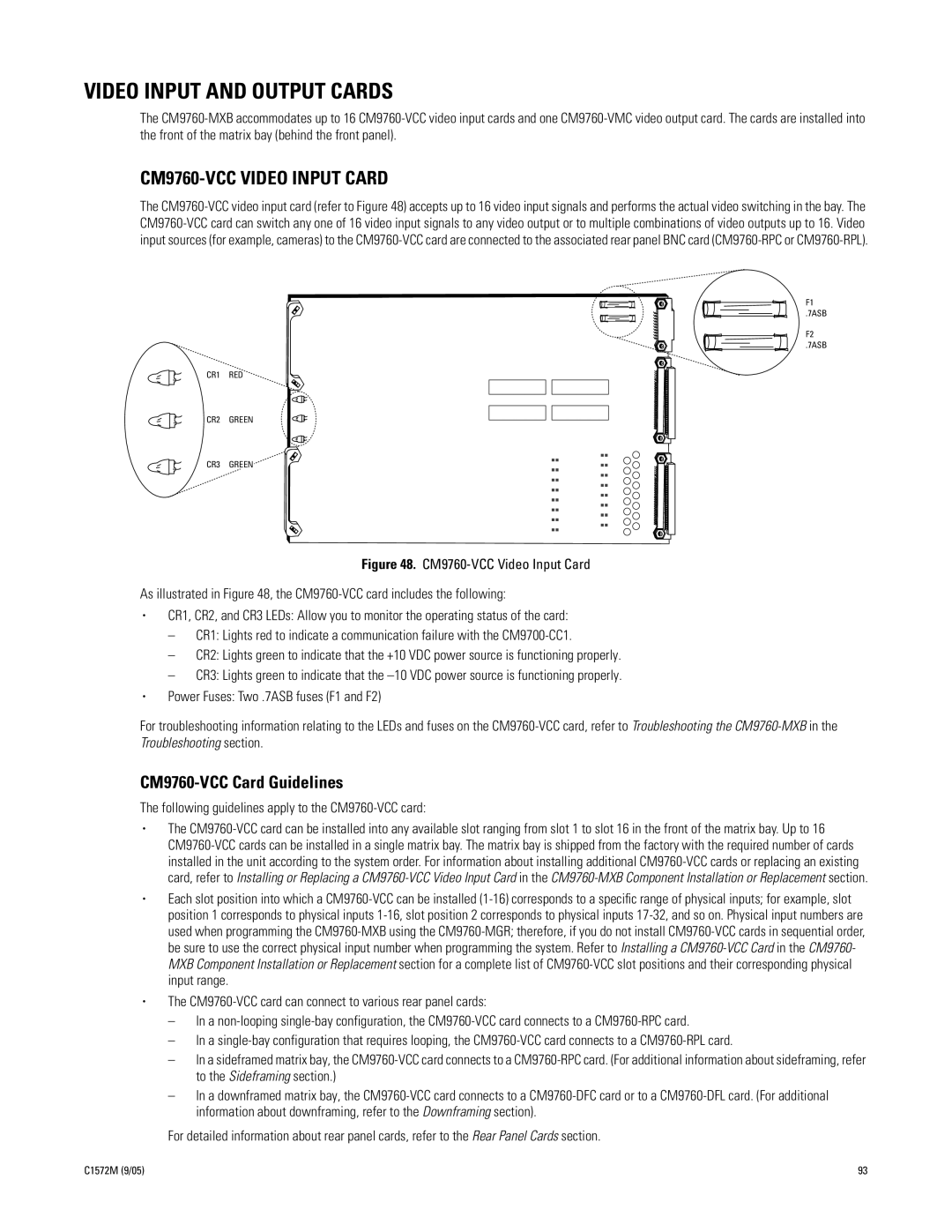
Figure 48. CM9760-VCC Video Input Card
As illustrated in Figure 48, the CM9760-VCC card includes the following:
•CR1, CR2, and CR3 LEDs: Allow you to monitor the operating status of the card:
–CR1: Lights red to indicate a communication failure with the CM9700-CC1.
–CR2: Lights green to indicate that the +10 VDC power source is functioning properly.
–CR3: Lights green to indicate that the –10 VDC power source is functioning properly.
•Power Fuses: Two .7ASB fuses (F1 and F2)
For troubleshooting information relating to the LEDs and fuses on the CM9760-VCC card, refer to Troubleshooting the CM9760-MXB in the Troubleshooting section.
CM9760-VCC Card Guidelines
The following guidelines apply to the CM9760-VCC card:
•The
•Each slot position into which a
•The
–In a
–In a
–In a sideframed matrix bay, the
–In a downframed matrix bay, the
For detailed information about rear panel cards, refer to the Rear Panel Cards section.
C1572M (9/05) | 93 |