Pelco System 9760 manual CM9700-CC1 Component Installation or Replacement

Models: System 9760

1 148
Download 148 pages 41.95 Kb
Page 31
Image 31

CM9700-CC1 Component Installation or Replacement

WARNINGS:

Installation or replacement of CM9700-CC1 components should be performed by qualified personnel only.

Electrostatic discharge (ESD) precautions must be observed when installing or replacing CM9700-CC1 components. Always wear a grounding strap connected to an approved grounding source when working on or near exposed electronic equipment.

This section provides information about the following:

Removing the top cover of the CM9700-CC1 (the top cover must be removed before CM9700-CC1 components can be installed or replaced)

Installing or replacing a CM9700-SER card

For information about replacing the VGA card (CM9700-CC1-VID) in the CM9700-CC1, refer to the CM9700-CC1-VID VGA Video Card Installation manual. For information about adding CM9700-SER-32 port expander units to the CM9700-CC1, refer to the CM9700-SER-32 Port Expander Installation/Operation manual.

REMOVING THE CM9700-CC1 TOP COVER

To remove the top cover of the CM9700-CC1, refer to Figure 15 and do the following:

1. Power off the CM9700-CC1.

WARNING: Failure to power off the CM9700-CC1 can result in serious damage to the equipment.

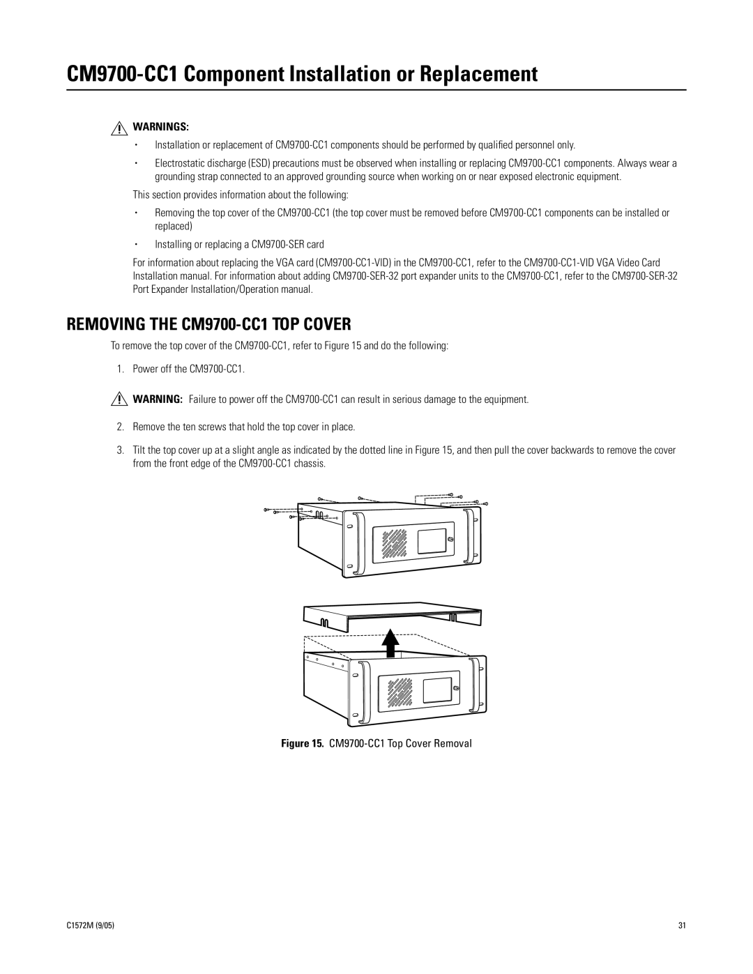
2.Remove the ten screws that hold the top cover in place.

3.Tilt the top cover up at a slight angle as indicated by the dotted line in Figure 15, and then pull the cover backwards to remove the cover from the front edge of the CM9700-CC1 chassis.

Figure 15. CM9700-CC1 Top Cover Removal

C1572M (9/05)

31

Page 31
Image 31
Pelco System 9760 manual CM9700-CC1 Component Installation or Replacement, Removing the CM9700-CC1 TOP Cover