Step 3
RUN THE REQUIRED WIRES (SEE ILLUSTRATION 2)
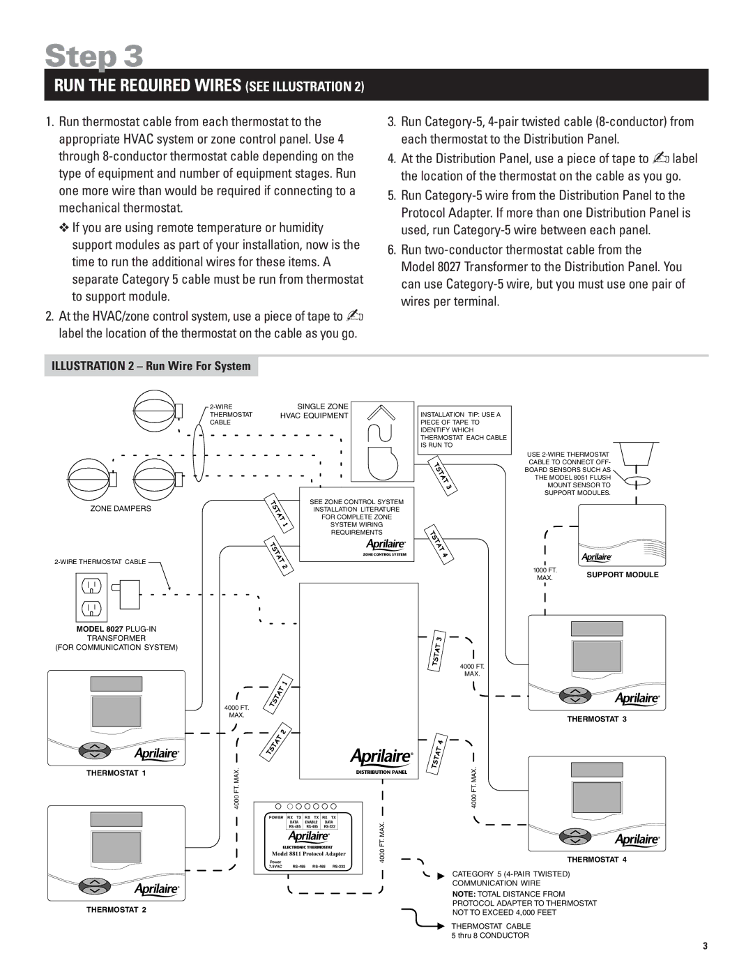
1.Run thermostat cable from each thermostat to the appropriate HVAC system or zone control panel. Use 4 through
❖If you are using remote temperature or humidity support modules as part of your installation, now is the time to run the additional wires for these items. A separate Category 5 cable must be run from thermostat to support module.
2.At the HVAC/zone control system, use a piece of tape to ✍ label the location of the thermostat on the cable as you go.
3.Run
4.At the Distribution Panel, use a piece of tape to ✍label the location of the thermostat on the cable as you go.
5.Run
6.Run
Model 8027 Transformer to the Distribution Panel. You can use
ILLUSTRATION 2 – Run Wire For System
ZONE DAMPERS
MODEL 8027
TRANSFORMER
(FOR COMMUNICATION SYSTEM)
THERMOSTAT 1
THERMOSTAT 2
SINGLE ZONE | |
THERMOSTAT | HVAC EQUIPMENT |
CABLE |
|
SEE ZONE CONTROL SYSTEM
INSTALLATION LITERATURE
FOR COMPLETE ZONE
SYSTEM WIRING
REQUIREMENTS
ZONE CONTROL SYSTEM
4000 FT.
MAX.
MAX.FT.4000 |
|
|
|
|
| DISTRIBUTION PANEL |
POWER RX TX | RX | TX | RX | TX |
| |
| DATA | ENABLE | DATA | MAX.FT. | ||
| ||||||
Power |
|
|
|
|
| 4000 |
Model 8811 Protocol Adapter |
| |||||
7.5VAC |
| |||||
INSTALLATION TIP: USE A
PIECE OF TAPE TO
IDENTIFY WHICH
THERMOSTAT EACH CABLE
IS RUN TO
USE
CABLE TO CONNECT OFF-
BOARD SENSORS SUCH AS
THE MODEL 8051 FLUSH
MOUNT SENSOR TO
SUPPORT MODULES.
1000 FT. |
|
| SUPPORT MODULE | ||
MAX. |
|
| |||
|
|
|
| ||
|
|
|
|
|
|
|
|
|
|
|
|
|
|
|
|
|
|
|
|
|
|
|
|
|
|
|
|
|
|
|
|
|
|
|
|
|
|
|
|
|
|
|
|
|
|
|
|
4000 FT.
MAX.
THERMOSTAT 3
4000 FT. MAX.
THERMOSTAT 4
CATEGORY 5
COMMUNICATION WIRE
NOTE: TOTAL DISTANCE FROM
PROTOCOL ADAPTER TO THERMOSTAT
NOT TO EXCEED 4,000 FEET
THERMOSTAT CABLE 5 thru 8 CONDUCTOR
3