Step 8
CONNECT PROTOCOL ADAPTER TO THE DISTRIBUTION PANEL AND HOST COMPUTER OR AUTOMATION SYSTEM
1.MAKE SURE THAT ALL SWITCHES IN THE DISTRIBUTION PANEL ARE OFF!
2.Use
3.Connect the
Some computers use
4.Power up the Protocol Adapter with the
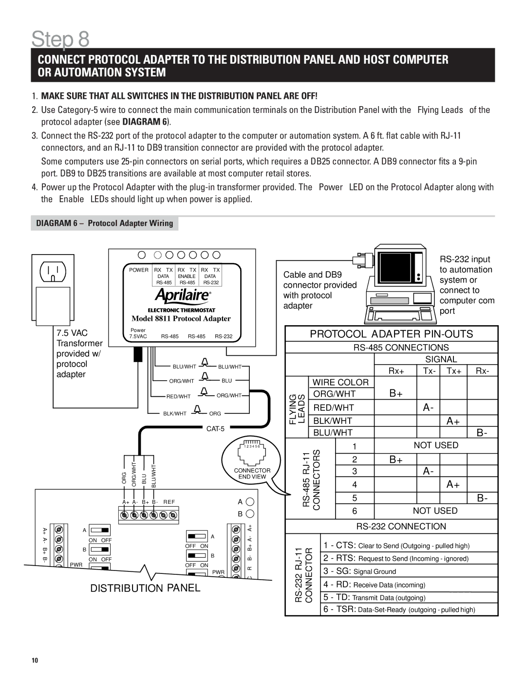
DIAGRAM 6 – Protocol Adapter Wiring
7.5VAC
Transformer provided w/ protocol adapter
POWER RX TX | RX TX RX TX | |||
| DATA | ENABLE | DATA | |
| ||||
Model 8811 Protocol Adapter | ||||
Power |
|
|
|
|
7.5VAC | ||||
|
| BLU/WHT |
| BLU/WHT |
| ORG/WHT |
| BLU | |
| RED/WHT |
| ORG/WHT | |
| BLK/WHT |
| ORG | |
|
|
|
| |
|
|
|
| 1 2 3 4 5 6 |
|
|
|
|
|
|
|
|
|
|
|
|
|
| |
|
|
|
|
|
|
|
|
|
|
|
|
|
| |
|
|
|
|
|
|
|
|
|
|
|
|
|
| to automation |
|
|
|
|
|
|
|
|
|
|
|
|
|
| |
Cable and DB9 |
|
|
|
|
|
|
|
| ||||||
|
|
|
|
| system or | |||||||||
connector provided |
|
|
|
|
|
|
|
| ||||||
|
|
|
|
|
|
|
| connect to | ||||||
|
|
|
|
| ||||||||||
with protocol |
|
|
|
|
|
|
|
|
|
|
| |||
|
|
|
|
|
|
|
|
|
|
| computer com | |||
adapter |
|
|
|
|
|
|
|
|
|
|
| port | ||
|
|
|
|
|
|
|
|
|
|
| ||||
|
|
|
|
|
|
|
|
|
|
|
|
|
| |
PROTOCOL ADAPTER PIN-OUTS
|
|
|
|
|
| SIGNAL | |||
|
|
|
| Rx+ |
| Tx- | Tx+ | Rx- | |
| WIRE COLOR |
| B+ |
|
|
|
|
| |
FLYING LEADS | ORG/WHT |
|
|
|
|
|
| ||
RED/WHT |
|
|
| A- |
|
|
| ||
|
|
|
|
|
|
|
|
| |
BLK/WHT |
|
|
|
| A+ |
|
| ||
| BLU/WHT |
|
|
|
|
| B- | ||
11 | 1 |
|
| NOT USED |
| ||||
|
|
|
|
|
|
|
|
| |
2 |
| B+ |
|
|
|
|
| ||
|
| ORG ORG/WHT BLU BLU/WHT |
|
| CONNECTOR |
|
|
|
| END VIEW | |
|
|
|
|
| |
|
| A+ A- B+ B- | REF |
| A |
|
|
|
|
| B |
A+ | A |
|
| A | A+ |
A- |
| ON OFF |
| A- | |
| OFF ON |
| |||
B+ | B |
|
| B+ | |
|
| B | |||
|
|
|
| - | |
B |
| ON OFF |
| B | |
|
|
| |||
- | PWR | OFF ON |
|
| |
|
|
| R | ||
|
|
|
| PWR | |
|
|
|
|
| |
|
| DISTRIBUTION PANEL |
|
| |
|
|
| 3 |
| A- | ||
|
| 4 |
| A+ | |||
|
|
|
|
|
|
| |
|
|
| 5 |
| B- | ||
|
| 6 |
| NOT USED |
| ||
|
|
|
|
| |||
|
|
|
|
|
|
| |
|
|
|
| ||||
|
|
|
| ||||
CONNECTOR | 1 | - CTS: Clear to Send (Outgoing - pulled high) | |||||
|
| ||||||
2 | - RTS: Request to Send (Incoming - ignored) | ||||||
3 | - SG: Signal Ground |
|
| ||||
|
| ||||||
4 | - RD: Receive Data (incoming) | ||||||
5 | - TD: Transmit Data (outgoing) | ||||||
|
| 6 | - TSR: | ||||
|
|
|
|
|
|
|
|
10