VR-CM50 specifications
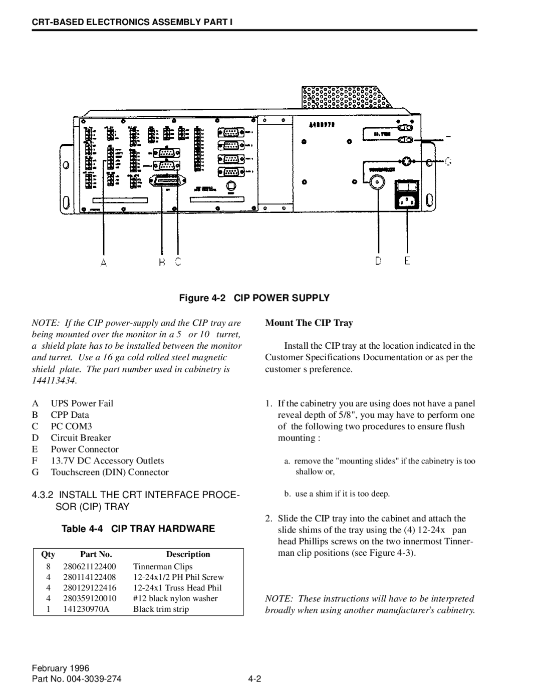
The EFJohnson VR-CM50 is a state-of-the-art mobile communications solution designed for first responders and public safety agencies. This versatile device is engineered to enhance communication efficiency and reliability, ensuring that users can stay connected in critical situations.The VR-CM50 features a rugged design, built to withstand the harsh environmental conditions often encountered by emergency personnel. It meets military specifications for durability, including shock, vibration, and water resistance. With a lightweight and compact form factor, the VR-CM50 is easy to install in various vehicles without compromising the available space or mobility.
One of the standout technologies in the VR-CM50 is its advanced digital trunking capability. The device operates on multiple frequency bands, allowing for seamless communication across various networks. This flexibility is crucial for interoperability among different agencies, especially during joint operations or mutual aid scenarios.
The VR-CM50 also offers enhanced audio quality, ensuring that users can clearly hear and be heard even in noisy environments. Its digital signal processing technology minimizes background noise and enhances voice clarity. This feature is vital for first responders who often communicate in high-pressure situations where every word counts.
Another key characteristic of the VR-CM50 is its integration with a wide range of communication systems. The device is compatible with various communication protocols, enabling connection with existing infrastructure. This adaptability allows agencies to leverage their current resources while benefiting from the latest technological advancements.
The VR-CM50 promotes user safety with built-in emergency features. It includes a dedicated emergency button that, when pressed, instantly alerts dispatchers and other personnel of the user's location and status. This feature is particularly beneficial for officers on patrol or in isolated areas, enhancing their safety during critical incidents.
Furthermore, the VR-CM50 supports GPS capabilities, providing real-time location tracking for fleet management and situational awareness. This technology not only improves operational efficiency but also enhances coordination during complex incidents.
In summary, the EFJohnson VR-CM50 is a robust and feature-rich mobile communication solution tailored for public safety professionals. Its rugged construction, advanced digital trunking, superior audio quality, and integration capabilities make it an essential tool for effective communication in the field. By fostering interoperability and user safety, the VR-CM50 stands as a reliable choice for agencies striving to enhance their emergency response capabilities.

