Appendix
Configurations of Terminals
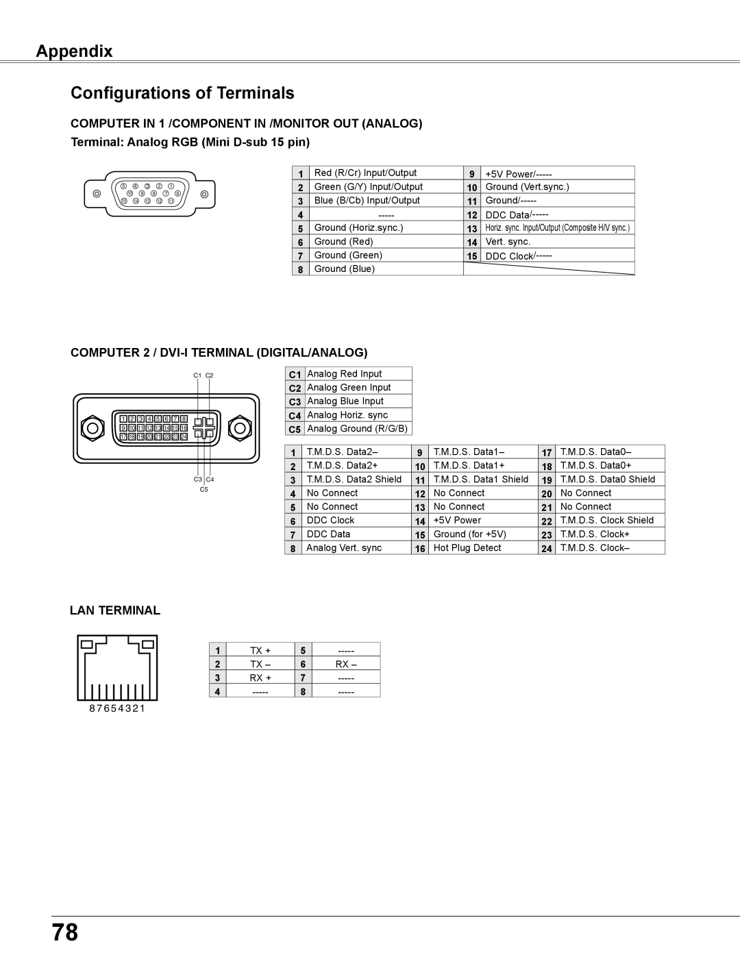
COMPUTER IN 1 /COMPONENT IN /MONITOR OUT (ANALOG) Terminal: Analog RGB (Mini
5 4 3 2 1
10 9 8 7 6
15 14 13 12 11
1 | Red (R/Cr) Input/Output | 9 | +5V |
2 | Green (G/Y) Input/Output | 10 | Ground (Vert.sync.) |
3 | Blue (B/Cb) Input/Output | 11 | |
4 | 12 | DDC | |
5 | Ground (Horiz.sync.) | 13 | Horiz. sync. Input/Output (Composite H/V sync.) |
6 | Ground (Red) | 14 | Vert. sync. |
7 | Ground (Green) | 15 | DDC |
8 | Ground (Blue) |
|
|
COMPUTER 2 / DVI-I TERMINAL (DIGITAL/ANALOG)
C1 C2
![]() 1
1 ![]()
![]() 2
2 ![]()
![]() 3
3 ![]()
![]() 4
4 ![]()
![]() 5
5 ![]()
![]() 6
6 ![]()
![]() 7
7 ![]()
![]() 8
8 ![]()
![]() 9
9 ![]()
![]() 10
10![]()
![]() 11
11![]()
![]() 12
12![]()
![]() 13
13![]()
![]() 14
14![]()
![]() 15
15![]()
![]() 16
16![]()
![]() 17
17![]()
![]() 18
18![]()
![]() 19
19![]()
![]() 20
20![]()
![]() 21
21![]()
![]() 22
22![]()
![]() 23
23![]()
![]() 24
24![]()
C3 C4
C5
C1 Analog Red Input
C2 Analog Green Input
C3 Analog Blue Input
C4 Analog Horiz. sync
C5 Analog Ground (R/G/B)
1 | T.M.D.S. Data2– | 9 | T.M.D.S. Data1– | 17 | T.M.D.S. Data0– |
2 | T.M.D.S. Data2+ | 10 | T.M.D.S. Data1+ | 18 | T.M.D.S. Data0+ |
3 | T.M.D.S. Data2 Shield | 11 | T.M.D.S. Data1 Shield | 19 | T.M.D.S. Data0 Shield |
4 | No Connect | 12 | No Connect | 20 | No Connect |
5 | No Connect | 13 | No Connect | 21 | No Connect |
6 | DDC Clock | 14 | +5V Power | 22 | T.M.D.S. Clock Shield |
7 | DDC Data | 15 | Ground (for +5V) | 23 | T.M.D.S. Clock+ |
8 | Analog Vert. sync | 16 | Hot Plug Detect | 24 | T.M.D.S. Clock– |
LAN TERMINAL
1 | TX + | 5 | |
2 | TX – | 6 | RX – |
3 | RX + | 7 | |
4 | 8 |
8 7 6 5 4 3 2 1
78