OPERATING INSTRUCTIONS
III . OPERATING INSTRUCTIONS
1.OPEN GAS BURNERS
The open gas burner incorporates a cover made of chrome nickel steel, a gas burner with ignition monitoring, and a finned pan rest. The finned pan rest is easily removed for cleaning.
The open burners can be operated from one side, or for half of the burners, from both sides of the range in question.
The outputs of the burners is 10 kW each.
Accessories:
HOTPLATE
The plate is laid on the finned burner pan rest. It can achieve high temperatures and is therefore suitable for both boiling and roasting. Several small saucepans can be placed on it. It has a higher heat storage capacity than the open burner.
It is used to keep food hot that has been cooked on the open burner. The output of the burner is accordingly low. Do not use this plate for main cooking or frying activities. The maximum temperature of the empty simmering plate may rise to 400°C.
4 | 2 | 1 |
5![]() 3
3
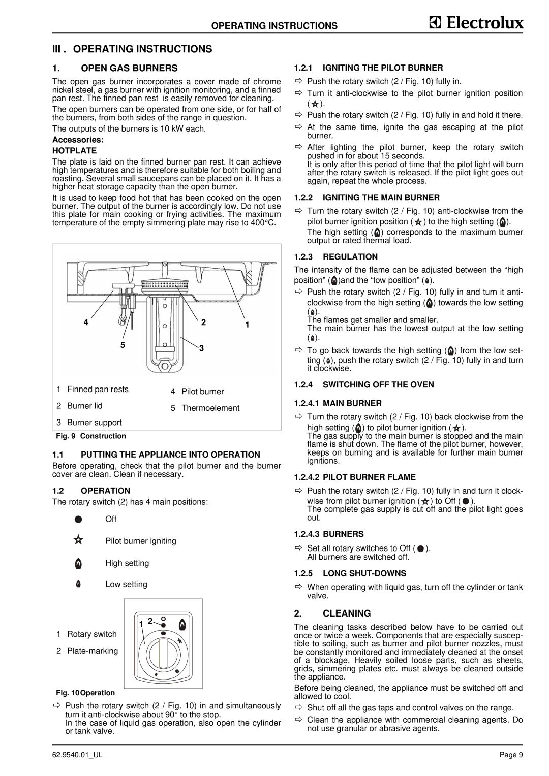
1 | Finned pan rests | 4 | Pilot burner |
2 | Burner lid | 5 | Thermoelement |
3Burner support
Fig. 9 Construction
1.1PUTTING THE APPLIANCE INTO OPERATION
Before operating, check that the pilot burner and the burner cover are clean. Clean if necessary.
1.2OPERATION
The rotary switch (2) has 4 main positions:
Off
Pilot burner igniting
High setting
Low setting
1.2.1IGNITING THE PILOT BURNER
DPush the rotary switch (2 / Fig. 10) fully in.
DTurn it ![]() ).
).
DPush the rotary switch (2 / Fig. 10) fully in and hold it there.
DAt the same time, ignite the gas escaping at the pilot burner.
DAfter lighting the pilot burner, keep the rotary switch pushed in for about 15 seconds.
It is only after this period of time that the pilot light will burn after the rotary switch is released. If the pilot light goes out again, repeat the whole process.
1.2.2IGNITING THE MAIN BURNER
DTurn the rotary switch (2 / Fig. 10)
pilot burner ignition position (![]() ) to the high setting (
) to the high setting (![]() ). The high setting ( ) corresponds to the maximum burner output or rated thermal load.
). The high setting ( ) corresponds to the maximum burner output or rated thermal load.
1.2.3REGULATION
The intensity of the flame can be adjusted between the “high position” (![]() )and the “low position” (
)and the “low position” (![]() ).
).
DPush the rotary switch (2 / Fig. 10) fully in and turn it anti-
clockwise from the high setting ( ) towards the low setting (![]() ).
).
The flames get smaller and smaller.
The main burner has the lowest output at the low setting (![]() ).
).
DTo go back towards the high setting ( ) from the low set- ting (![]() ), push the rotary switch (2 / Fig. 10) fully in and turn it clockwise.
), push the rotary switch (2 / Fig. 10) fully in and turn it clockwise.
1.2.4SWITCHING OFF THE OVEN
1.2.4.1 MAIN BURNER
DTurn the rotary switch (2 / Fig. 10) back clockwise from the
high setting ( ) to pilot burner ignition ( ).
The gas supply to the main burner is stopped and the main flame is shut down. The flame of the pilot burner, however, keeps on burning and is available for further main burner ignitions.
1.2.4.2 PILOT BURNER FLAME
DPush the rotary switch (2 / Fig. 10) fully in and turn it clock-
wise from pilot burner ignition ( ) to Off ( ![]() ).
).
The complete gas supply is cut off and the pilot light goes out.
1.2.4.3 BURNERS
DSet all rotary switches to Off ( ![]() ). All burners are switched off.
). All burners are switched off.
1.2.5LONG SHUT-DOWNS
DWhen operating with liquid gas, turn off the cylinder or tank valve.
1Rotary switch
2
Fig. 10Operation
1 2![]()
![]()
![]()
2.CLEANING
The cleaning tasks described below have to be carried out once or twice a week. Components that are especially suscep- tible to soiling, such as burner and pilot burner nozzles, must be constantly monitored and immediately cleaned at the onset of a blockage. Heavily soiled loose parts, such as sheets, grids, simmering plates etc. must always be cleaned outside the appliance.
Before being cleaned, the appliance must be switched off and allowed to cool.
DPush the rotary switch (2 / Fig. 10) in and simultaneously turn it
In the case of liquid gas operation, also open the cylinder or tank valve.
DShut off all the gas taps and control valves on the range.
DClean the appliance with commercial cleaning agents. Do not use granular or abrasive agents.
62.9540.01_UL | Page 9 |