OPERATING INSTRUCTIONS
4.
The roasting and baking oven is integrated in the base unit of the range. The oven equipment includes:
-removable grid guides
-grid and trays
The base of the oven is made of a thick steel plate which dis- tributes and stores the heat evenly. All other parts of the appli- ance are made of chrome nickel steel. The power rating is 7 kW.
Note
•It should be noted that hot air or steam flows out when the door is opened - Danger of burns!
•Particular care must be taken when the oven door is open - otherwise the operator may injure or burn his legs.
WARNING
•Use always the straight part of the oven door handle. Do not touch the curves of the oven door handle, it can be hot. - Danger of burns!
4.1OPERATION
1
2Temperature selector switch
Fig. 13Operating panel
4.1.1SWITCHING ON
DPress the rotary switch in and simultaneously turn it anti- clockwise to the stop.
When operating with liquid gas also open the cylinder or tank valve.
DTurn the On/Off switch (1 / Fig. 13) towards Ignition as far as the stop.
DPress and wait a few seconds. (Only ignition gas flows then).
DWhile still pressing, turn it further to the left. Ignition is then completed by the piezo ignition device. When the pilot light is burning, keep pressing for 10 seconds. If the pilot light does not burn, steps 1 and 2 can be repeated immediately.
DOnce the pilot light is burning, release the switch.
DTurn further to the left in the burner setting.
Ignition gas flows and, depending on the temperature selection switch (2 / Fig. 13), also the main gas.
4.1.2TEMPERATURE SETTING
The baking oven temperature can be adjusted by turning the temperature selection switch (2 / Fig. 13).
4.1.3SWITCHING OFF
DTurn the On/Off switch (1 / Fig. 13) to the right as far as the stop. In this position only the ignition gas burns.
DTo switch off completely, press the knob lightly and turn to Off. Only when the
DTurn off the gas tap on the control panel.
When operating with liquid gas, turn off the cylinder or tank valve.
4.1.4HEATING AND REGULATION
Turning the temperature selection switch (2 / Fig. 13) anti- clockwise causes the main burner to ignite automatically. The oven temperature can be set steplessly and is regulated ther- mostatically. The rotary switch has a scale from 1 to 7. In the steady state the various scale numbers correspond approxi- mately to the following oven temperatures:
Level | Oven temperature | |
| °F | °C |
|
|
|
1 | 257 | 125 |
|
|
|
2 | 309 | 154 |
|
|
|
3 | 361 | 183 |
|
|
|
4 | 414 | 212 |
|
|
|
5 | 468 | 242 |
|
|
|
6 | 522 | 272 |
|
|
|
7 | 572 | 300 |
|
|
|
As soon as the preset oven temperature is reached, the main burner is adjusted modulating.
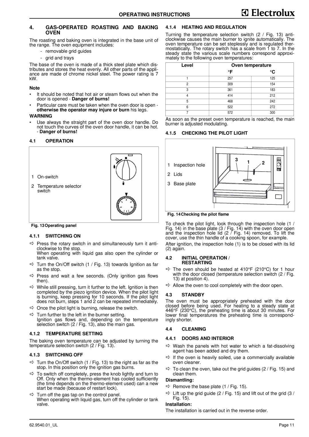
4.1.5CHECKING THE PILOT LIGHT
1 Inspection hole | 3 | 1 | 2 |
| |||
|
|
|
2Lids
3Base plate
Fig. 14Checking the pilot flame
To check the pilot light, look through the inspection hole (1 / Fig. 14) in the base plate (3 / Fig. 14) with the oven door open and the inspection hole lid (2 / Fig. 14) removed. To lift the cover, use the thin handle of a cooking spoon, for example.
After ignition, the inspection hole (1) is to be closed with its lid
(2) again.
4.2INITIAL OPERATION / RESTARTING
DThe oven should be heated at 410°F (210°C) for 1 hour with the door closed (temperature selection switch (2 / Fig. 13) at position 4).
DAllow the oven to cool completely with the door open.
4.3STANDBY
The oven must be appropriately preheated with the door closed before being used. For heating to a steady state at 446°F (230°C), the preheating time is about 30 minutes. For lower final temperatures the preheating time is correspond- ingly shorter.
4.4CLEANING
4.4.1DOORS AND INTERIOR
DWash the panels with hot water to which a
DIf the oven is heavily soiled, use a commercially available oven cleaner.
DTo clean the oven, take out the grid guides (2 / Fig. 15) and clean them.
Dismantling:
DRemove the base plate (1 / Fig. 15).
DLift up the grid guide (2 / Fig. 15) and lift out of the grid (3 / Fig. 15).
Installation:
The installation is carried out in the reverse order.
62.9540.01_UL | Page 11 |