ASSEMBLY OF THE CONSOLE
TO THE HANDLEBAR
Attach the bracket to the handlebar, preferably close to the stem. To block the bracket, position the bolt lever as shown in illustration 8. The bolt regulation of the bracket can be adjusted for a secure fix to the handlebar. It may be necessary to remove one or both the rubber shims from the bracket in order to fit larger diameter handlebars.
Illustration 9 shows the correct position of the console mounted to the handlebar.
Check the console is securely fixed to the handlebar and slightly inclined before starting.
9
GB
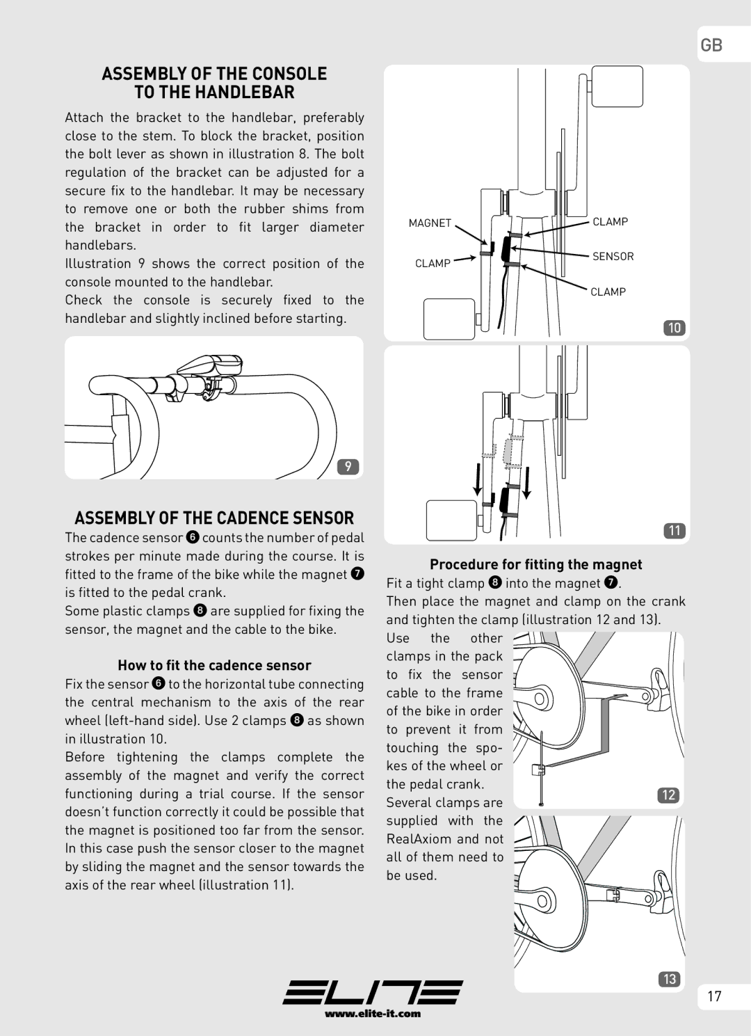
MAGNET | CLAMP |
CLAMP | SENSOR |
| |
| CLAMP |
10
ASSEMBLY OF THE CADENCE SENSOR
The cadence sensor 6 counts the number of pedal strokes per minute made during the course. It is fitted to the frame of the bike while the magnet 7 is fitted to the pedal crank.
Some plastic clamps 8 are supplied for fixing the sensor, the magnet and the cable to the bike.
How to fit the cadence sensor
Fix the sensor 6 to the horizontal tube connecting the central mechanism to the axis of the rear wheel
Before tightening the clamps complete the assembly of the magnet and verify the correct functioning during a trial course. If the sensor doesn’t function correctly it could be possible that the magnet is positioned too far from the sensor. In this case push the sensor closer to the magnet by sliding the magnet and the sensor towards the axis of the rear wheel (illustration 11).
11
Procedure for fitting the magnet
Fit a tight clamp 8 into the magnet 7.
Then place the magnet and clamp on the crank | |||||
and tighten the clamp (illustration 12 and 13). |
| ||||
Use | the | other |
| ||
clamps in the pack |
| ||||
to fix | the | sensor |
| ||
cable to the frame |
| ||||
of the bike in order |
| ||||
to prevent | it | from |
| ||
touching the | spo- |
| |||
kes of the wheel or |
| ||||
the pedal crank. | 12 | ||||
Several clamps are | |||||
| |||||
supplied with | the |
| |||
RealAxiom and not |
| ||||
all of them need to |
| ||||
be used. |
|
|
| ||
13
17