GB
ASSEMBLING INSTRUCTIONS
WARNING. NOTE. DO NOT CONNECT THE USB CABLE TO THE COMPUTER
BEFORE INSTALLING THE REALAXIOM SOFTWARE.
SEMPLIFIED GENERAL DIAGRAM
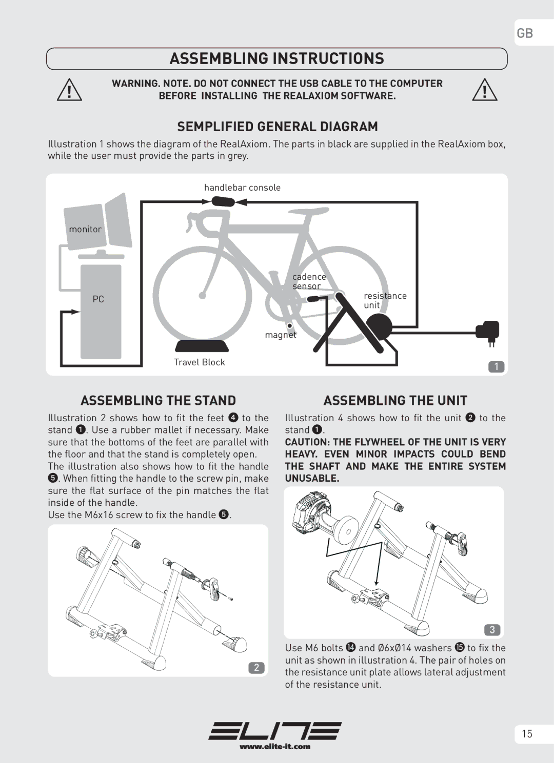
Illustration 1 shows the diagram of the RealAxiom. The parts in black are supplied in the RealAxiom box, while the user must provide the parts in grey.
monitor |
PC |
handlebar console
cadence sensor
resistance unit
magnet
Travel Block | 1 |
|
ASSEMBLING THE STAND | ASSEMBLING THE UNIT |
Illustration 2 shows how to fit the feet 4 to the stand 1. Use a rubber mallet if necessary. Make sure that the bottoms of the feet are parallel with the floor and that the stand is completely open.
The illustration also shows how to fit the handle 5. When fitting the handle to the screw pin, make sure the flat surface of the pin matches the flat inside of the handle.
Use the M6x16 screw to fix the handle 5.
2
Illustration 4 shows how to fit the unit 2 to the stand 1.
CAUTION: THE FLYWHEEL OF THE UNIT IS VERY HEAVY. EVEN MINOR IMPACTS COULD BEND THE SHAFT AND MAKE THE ENTIRE SYSTEM UNUSABLE.
3
Use M6 bolts N and Ø6xØ14 washers O to fix the unit as shown in illustration 4. The pair of holes on the resistance unit plate allows lateral adjustment of the resistance unit.
15