Rear Panel
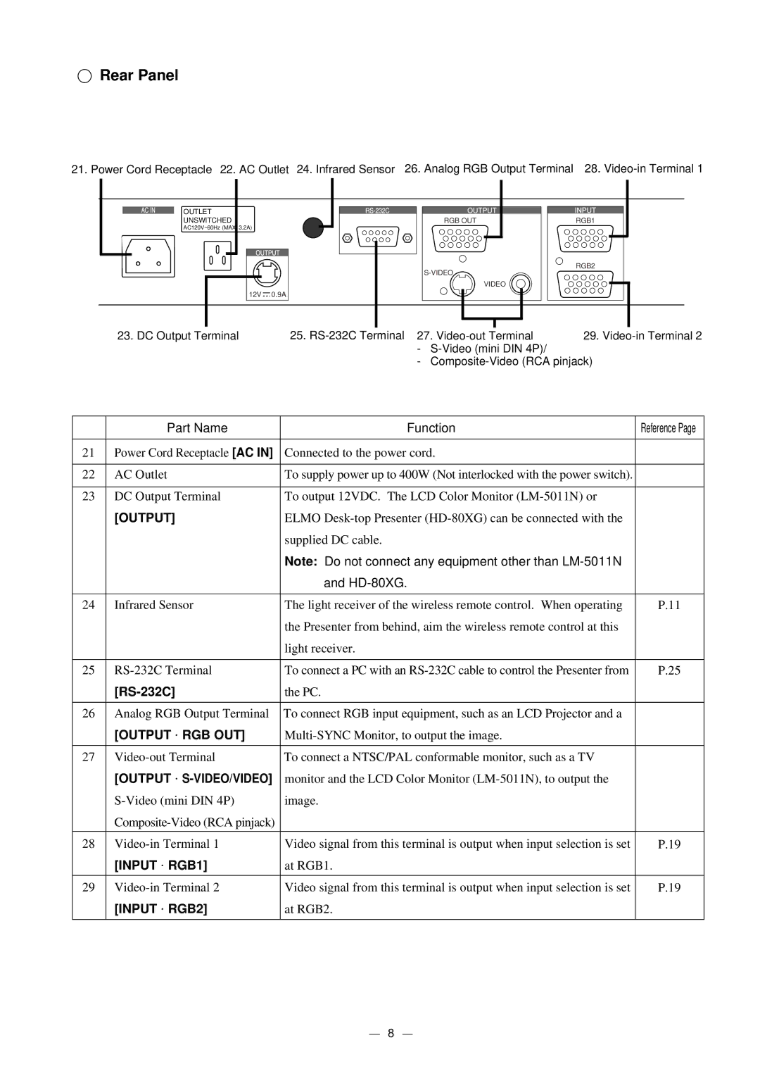
21. Power Cord Receptacle 22. AC Outlet 24. Infrared Sensor 26. Analog RGB Output Terminal 28.
OUTLET
UNSWITCHED
AC120V~60Hz (MAX. 3.2A)
12V ![]() 0.9A
0.9A
RGB OUT
VIDEO
RGB1
RGB2
| 23. DC Output Terminal | 25. | 29. | |
|
| - |
|
|
|
| - |
| |
|
|
|
|
|
| Part Name | Function |
| Reference Page |
|
|
|
|
|
21 | Power Cord Receptacle [AC IN] | Connected to the power cord. |
|
|
|
|
|
| |
22 | AC Outlet | To supply power up to 400W (Not interlocked with the power switch). |
| |
|
|
|
| |
23 | DC Output Terminal | To output 12VDC. The LCD Color Monitor |
| |
| [OUTPUT] | ELMO |
| |
|
| supplied DC cable. |
|
|
|
| Note: Do not connect any equipment other than |
| |
|
| and |
|
|
|
|
|
| |
24 | Infrared Sensor | The light receiver of the wireless remote control. When operating | P.11 | |
|
| the Presenter from behind, aim the wireless remote control at this |
| |
|
| light receiver. |
|
|
|
|
|
| |
25 | To connect a PC with an | P.25 | ||
|
| the PC. |
|
|
|
|
|
| |
26 | Analog RGB Output Terminal | To connect RGB input equipment, such as an LCD Projector and a |
| |
| [OUTPUT ⋅ RGB OUT] |
|
| |
|
|
|
| |
27 | To connect a NTSC/PAL conformable monitor, such as a TV |
| ||
| [OUTPUT ⋅ | monitor and the LCD Color Monitor |
| |
| image. |
|
| |
|
|
|
| |
|
|
|
| |
28 | Video signal from this terminal is output when input selection is set | P.19 | ||
| [INPUT ⋅ RGB1] | at RGB1. |
|
|
29 | Video signal from this terminal is output when input selection is set | P.19 | ||
| [INPUT ⋅ RGB2] | at RGB2. |
|
|
|
|
|
|
|
8