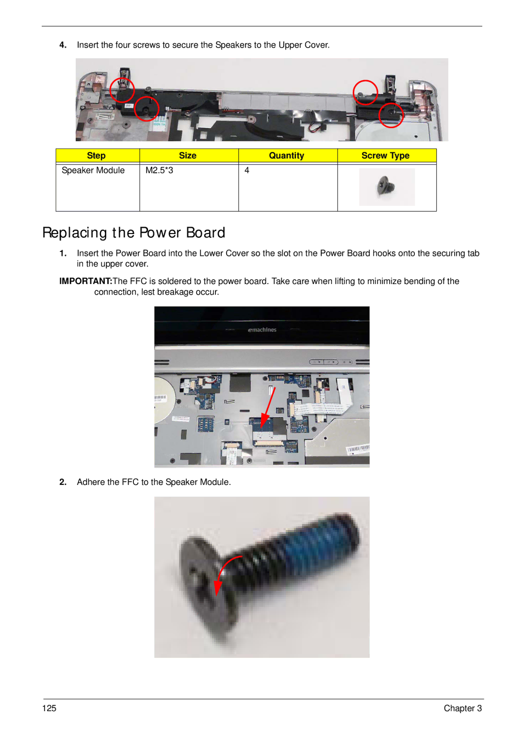
4.Insert the four screws to secure the Speakers to the Upper Cover.
Step |
| Size | Quantity | Screw Type |
|
|
|
|
|
Speaker Module | M2.5*3 |
| 4 |
|
|
|
|
|
|
Replacing the Power Board
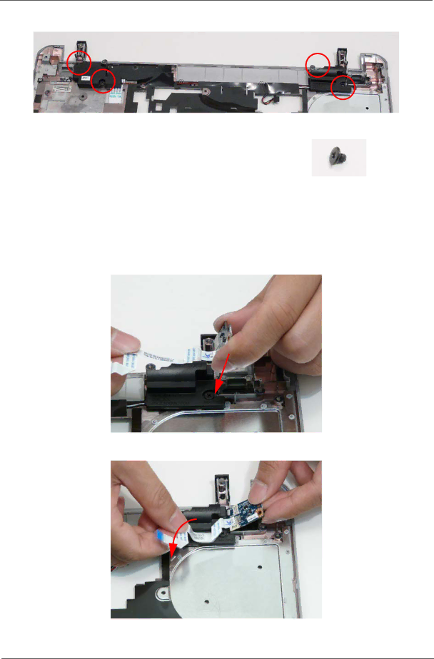
1.Insert the Power Board into the Lower Cover so the slot on the Power Board hooks onto the securing tab in the upper cover.
IMPORTANT:The FFC is soldered to the power board. Take care when lifting to minimize bending of the connection, lest breakage occur.
2.Adhere the FFC to the Speaker Module.
125 | Chapter 3 |