Manuals
/
Brands
/
Computer Equipment
/
Laptop
/
eMachines
/
Computer Equipment
/
Laptop
eMachines
E628
- page 56
1
56
224
224
Download
224 pages, 7.32 Mb
Chapter 3
46
Removing the Hard Disk Drive Module
1.
See “Removing the Battery Pack” on page 45
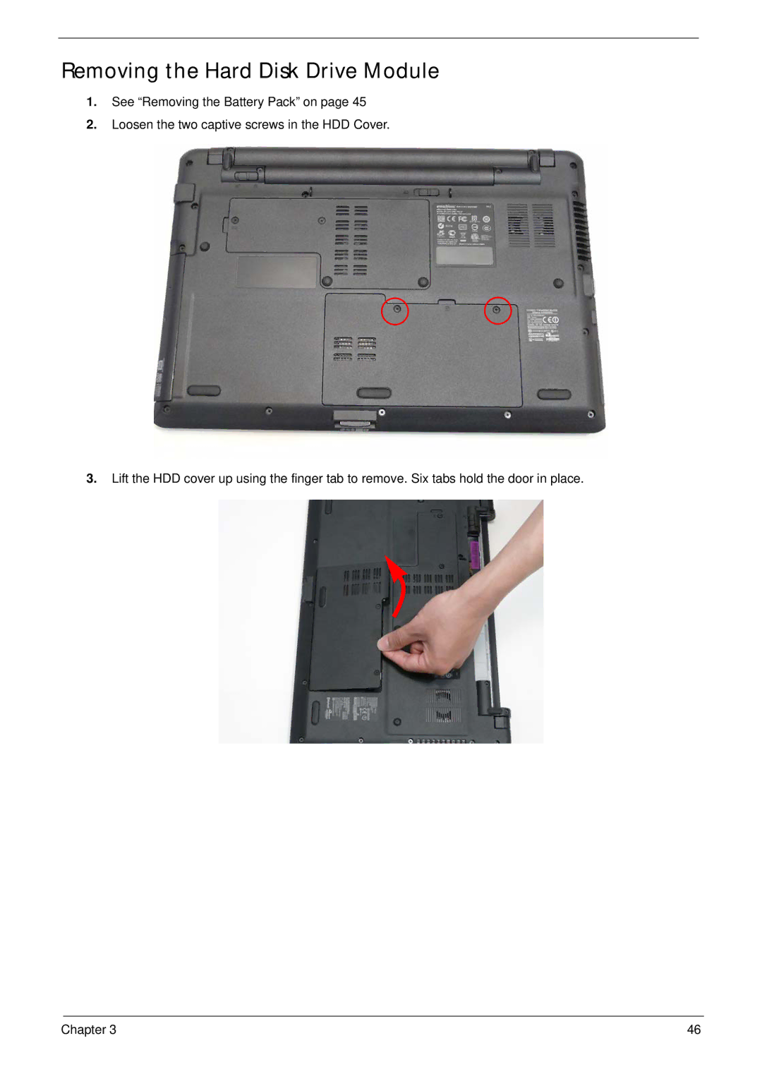
2.
Loosen the two
captive scre
ws in the HDD Cover .
3.
Lift the HDD cover up using the finger tab to
re mo
ve. Six tabs hold the door in place.
Contents
Main
Page
Copyright
Disclaimer
Conventions
Preface
Page
System Specifications 1
System Utilities 23
Machine Disassembly and Replacement 42
Troubleshooting 148
Jumper and Connector Locations 173
FRU (Field Replaceable Unit) List 177
Model Definition and Configuration 190 Test Compatible Components 206
Online Support Information 210 Index 211
Page
System Specifications
Chapter 1
Features
Page
Page
4Chapter 1
System Block Diagram
ENE KB926
AMD S1G1 Processor
ATI RS780MN
ATI SB710
Your Notebook Tour
Front View
Closed Front View
Left View
Right View
Base View
Rear View
Indicators
TouchPad Basics
Using the Keyboard
Lock Keys and embedded numeric keypad
Windows Keys
Hot Keys
Special Keys
Hardware Specifications and Configurations
Page
Page
Page
Page
Page
Page
Page
System Utilities
Chapter 2
BIOS Setup Utility
Navigating the BIOS Utility
Information
Main
Advanced
Page
Security
Page
Page
Power
Boot
Exit
Page
DOS Flash Utility
Page
Remove HDD/BIOS Password Utilities
Page
Miscellaneous Utilities
Using Boot Sequence Selector
Using DMITools
Example 1: Read DMI Information from Memory
Example 2: Write Product Name to EEPROM
Using the LAN MAC Utility
Page
Machine Disassembly and Replacement
Chapter 3
Disassembly Requirements
Related Information
General Information
Pre-disassembly Instructions
Disassembly Process
External Module Disassembly Process
External Modules Disassembly Flowchart
Page
Page
Page
Page
Page
Page
Page
Page
Page
Page
Page
Page
Page
Main Unit Disassembly Process
Main Unit Disassembly Flowchart
Page
Removing the Keyboard
Page
Page
Page
Page
Page
Page
Page
Removing the Touchpad Bracket
Page
Page
Page
Page
Page
Page
Page
Page
Page
Page
Page
Page
Page
Page
Page
Page
Page
Page
Removing the Thermal Module
Page
LCD Module Disassembly Process
LCD Module Disassembly Flowchart
Removing the LCD Bezel
Page
Page
Page
Page
Page
Page
Page
Page
Page
Page
Page
Page
Page
Page
Page
Page
Page
Page
Page
Page
Page
Page
Page
Page
Page
Page
Page
Page
Page
Page
Page
Page
Page
Page
Replacing the Power Board
Page
Page
Page
Page
Page
Page
Page
Page
Page
Page
Page
Replacing the DIMM Modules
Page
Page
Page
Page
Page
Page
Page
Page
Page
Page
Troubleshooting
Chapter 4
Common Problems
Power On Issue
Computer Shutsdown Intermittently
No Display Issue
No POST or Video
Abnormal Video Display
Random Loss of BIOS Settings
Page
Page
Sound Problems
Internal Microphone Failure
Microphone Problems
HDD Not Operating Correctly
ODD Failure
ODD Not Operating Correctly
Discs Do Not Play
Discs Do Not Burn Properly
Playback is Choppy
Drive Not Detected
Drive Read Failure
Page
161 Chapter 4
Wireless Function Failure
Chapter 4 162
Bluetooth Function Failure
Easy Button Failure
163 Chapter 4
Thermal Unit Failure
External Mouse Failure
Other Failures
Intermittent Problems
Undetermined Problems
POST Code Tables
Sec
Memory
DLL Timing Control Registers, RCOMP settings
BDS & Specific action:
Each PEIM entry point used in 80_PORT
Page
Page
Page
Page
Jumper and Connector Locations
Chapter 5
Top View
Bottom View
Clearing Password Check and BIOS Recovery
Clearing Password Check
Hardware Open Gap Description
Steps for Clearing BIOS Password Check
BIOS Recovery by Crisis Disk
BIOS Recovery Boot Block:
BIOS Recovery Hotkey:
Steps for BIOS Recovery from USB Storage:
FRU (Field Replaceable Unit) List
Chapter 6
Aspire 5538 Exploded Diagrams
Main Assembly
LCD Assembly
Aspire 5538 FRU List
Page
Page
Page
Page
Page
Page
Screw List
Page
Page
Appendix A 190
Model Definition and Configuration
Appendix A
Aspire 5538 Series
191 Appendix A
Appendix A 192
193 Appendix A
Appendix A 194
195 Appendix A
Appendix A 196
197 Appendix A
Model Memory 1Memory
SW1 Card
2HDD 1(GB) ODD Extra
Appendix A 198
Model Memory 1Memory
SW1 Card
2HDD 1(GB) ODD Extra
199 Appendix A
Model Memory 1Memory
SW1 Card
2HDD 1(GB) ODD Extra
Appendix A 200
Model Wireless LAN Wireless
Model Memory 1Memory
SW1 Card
2HDD 1(GB) ODD Extra
201 Appendix A
Model Wireless LAN Wireless
Appendix A 202
Model Wireless LAN Wireless
203 Appendix A
Model Wireless LAN Wireless
Appendix A 204
Model Wireless LAN Wireless
Page
Test Compatible Components
Appendix B
Windows XP Environment Test
Page
Page
Online Support Information
Appendix C
Index
A
B
C
D
J
K
L
M
N
U
V
W